The document consists of the following major sections:
Getting Started
This section provides a brief introduction of ESP32-S3-DevKitC-1, instructions on how to do the initial hardware setup and how to flash firmware onto it.
Description of Components
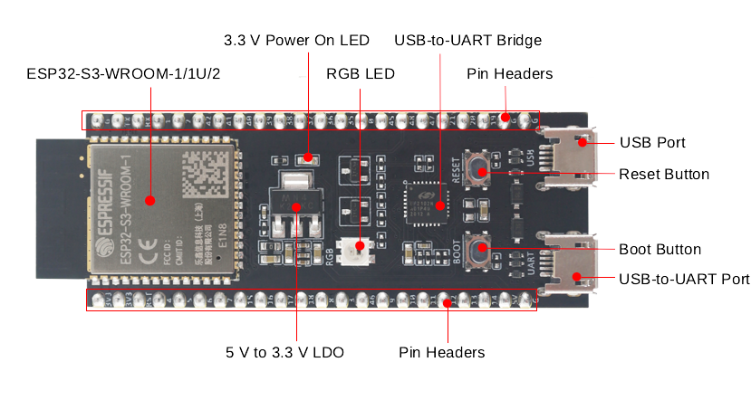
ESP32-S3-DevKitC-1 - front
The key components of the board are described in a counter-clockwise direction.
|
Key Component
|
Description
|
|---|
|
ESP32-S3-WROOM-1/1U/2
|
ESP32-S3-WROOM-1, ESP32-S3-WROOM-1U, and ESP32-S3-WROOM-2 are powerful, generic Wi-Fi + Bluetooth LE MCU modules that have a rich set of peripherals. They provide acceleration for neural network computing and signal processing workloads. ESP32-S3-WROOM-1 and ESP32-S3-WROOM-2 comes with a PCB antenna. ESP32-S3-WROOM-1U comes with an external antenna connector.
|
|
5 V to 3.3 V LDO
|
Power regulator that converts a 5 V supply into a 3.3 V output.
|
|
Pin Headers
|
All available GPIO pins (except for the SPI bus for flash) are broken out to the pin headers on the board for easy interfacing and programming. For details, please see Header Block.
|
|
USB-to-UART Port
|
A Micro-USB port used for power supply to the board, for flashing applications to the chip, as well as for communication with the chip via the on-board USB-to-UART bridge.
|
|
Boot Button
|
Download button. Holding down Boot and then pressing Reset initiates Firmware Download mode for downloading firmware through the serial port.
|
|
Reset Button
|
Press this button to restart the system.
|
|
ESP32-S3 USB Port
|
ESP32-S3 full-speed USB OTG interface, compliant with the USB 1.1 specification. The interface is used for power supply to the board, for flashing applications to the chip, for communication with the chip using USB 1.1 protocols, as well as for JTAG debugging.
|
|
USB-to-UART Bridge
|
Single USB-to-UART bridge chip provides transfer rates up to 3 Mbps.
|
|
RGB LED
|
Addressable RGB LED, driven by GPIO48.
|
|
3.3 V Power On LED
|
Turns on when the USB power is connected to the board.
|
Note
For boards with Octal SPI flash/PSRAM memory embedded ESP32-S3-WROOM-1/1U modules, and boards with ESP32-S3-WROOM-2 modules, the pins GPIO35, GPIO36 and GPIO37 are used for the internal communication between ESP32-S3 and SPI flash/PSRAM memory, thus not available for external use.
Start Application Development
Before powering up your board, please make sure that it is in good condition with no obvious signs of damage.
Required Hardware
-
ESP32-S3-DevKitC-1
-
USB 2.0 cable (Standard-A to Micro-B)
-
Computer running Windows, Linux, or macOS
Note
Be sure to use an appropriate USB cable. Some cables are for charging only and do not provide the needed data lines nor work for programming the boards.
Hardware Setup
Connect the board with the computer using USB-to-UART Port. Connection using ESP32-S3 USB Port is not fully implemented in software. In subsequent steps, USB-to-UART Port will be used by default.
Software Setup
Please proceed to Get Started, where Section Installation will quickly help you set up the development environment and then flash an application example onto your board.
Contents and Packaging
Product Information
|
Product
|
Module Integrated
|
Flash
|
PSRAM
|
SPI Voltage
|
|---|
|
|
|
|
|
|
|
ESP32-S3-DevKitC-1-N8R8
|
ESP32-S3-WROOM-1-N8R8
|
8 MB QD
|
8 MB OT
|
3.3 V
|
|
|
|
|
|
|
Note
In the table above, QD stands for Quad SPI and OT stands for Octal SPI.