• Banner

D4184 MOSFET Control Module Robotics Bangladesh
  • D4184 MOSFET Control Module Robotics Bangladesh

D4184 MOSFET Control Module

RBD-2757

N-Channel logic compatible MOSFET with optoisolation and low Rds(on).

BDT 150.00
BDT 150.00 BDT 150.00 BDT 150.00 BDT 150.00
Tax included Tax excluded Tax included Tax excluded
BDT 150.00 Tax excluded
BDT 150.00 Tax included
BDT 0.00 Tax
BDT 150.00 Tax excluded
BDT 0.00 Tax
BDT 150.00 Tax included
Quantity
30 Items

  Security policy

(edit with the Customer Reassurance module)

  Delivery policy

(edit with the Customer Reassurance module)

  Return policy

(edit with the Customer Reassurance module)

Description

DESCRIPTION

This MOSFET module with optoisolation uses the D4184 N-Channel logic compatible MOSFET with low Rds(on) for moderate to higher current low-side switching applications.

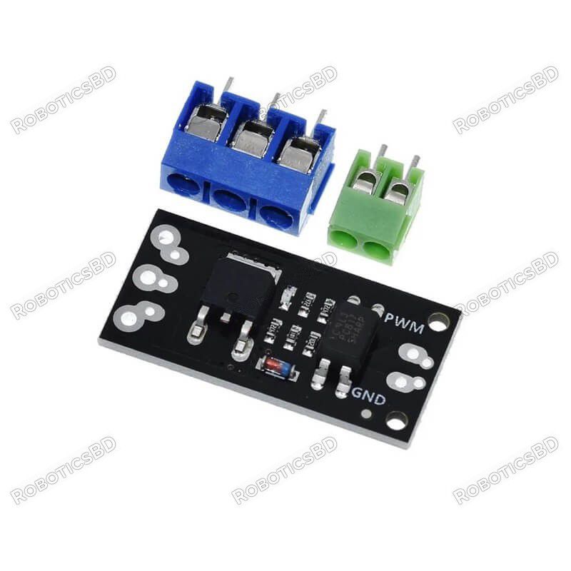
PACKAGE INCLUDES:

  • D4184 MOSFET Control Module
  • 3-pin Screw Terminal
  • 2-pin Screw Terminal
  • Small male header strip

KEY FEATURES OF D4184 MOSFET CONTROL MODULE:

  • One switching output
  • Low 8.5mΩ Rds(on) resistance
  • 2.5V – 20V input control voltage with optoisolation
  • 6 – 36V output switching voltage
  • 10A continuous current handling capability (See notes below)
  • 3.3 and 5V logic compatible (See notes below)

The modules utilizes the D4184 N-channel MOSFET that has a low Rds(on) resistance of 8.5mΩ typical.

These modules support about 10A of continuous current with a load voltage of 12V.  If driven with PWM, the maximum peak current can be greater up to 20A or more.

The design of these modules includes an optoisolator on the input so the input is biased from the output load voltage and is independent of logic levels used for the drive signal.  A 3.3V input will drive as much current as a 5V input for instance.

Note that the module does not have a fly-back diode on the board.  If using the module with inductive loads, an external fly-back diode should be used to avoid possible damage.

Theory of Operation

D4184 MOSFET Control Module Schematic

The module includes a PC817 optoisolator which provides electrical isolation between the high powered MOSFET side and the logic signals used to control the module.  If something goes wrong and you burn up the MOSFET, it should not damage the MCU being used to control it.

The MCU PWM input to the module drives the internal LED side of the optoisolator.  This input includes a 1K ohm series current limiting resistor to keep the current through the LED at safe levels which allows the input to be driven by up to a 20V input or even higher if you are not using an MCU.

When the PWM input signal is low or disconnected, the internal LED in the optoisolator is off which in turn keeps the phototransistor output turned off.  With the phototransistor off, the gate of the MOSFET is pulled to ground by a 4.7K resistor.  This keeps the MOSFET turned off and the load is disconnected from ground and disbled.

A logic high on the PWM input turns on the internal optoisolator LED which turns on the phototransistor.  This creates a voltage divider composed primarily of two 4.7K resistors.  This biases the gate at 50% of the power supply voltage which turns on the MOSFET.  If a 12V power supply is used, the gate will be at 6V.

Since the maximum gate voltage available to turn on the MOSFET is 50% of the power supply voltage, that limits the power supply to a minimum of about 6V.  Power dissipation in the MOSFET will be higher with lower power supply voltages and a minimum power supply of 9V is recommended if trying to draw more than a few amps through the module.

When the MOSFET conducts, the load is connected to ground to complete the circuit and the load is powered up.  This also provides a ground for the on-board LED which lights to indicate that the MOSFET is turned on.  A 4.7K resistor limits current through the on-board LED to safe levels over the 6-36V operating range.

Module Connections

The module requires 3 connections.  A logic signal to turn the MOSFET on/off; a DC power supply to power the device (load) being controlled and finally the load itself.  Connectors are provided that can be soldered to be the board, but these connections can also be made by direct wiring if desired.

D4148 MOSFET Control Module - Connections

D4148 MOSFET Control Module – Connections

Logic Signal Connections:  The 2-pin connector on the right side is for making connections to the MCU.  It has two holes on 4mm centers which support a 2 position screw terminal as well as two holes on 0.1″ centers that can alternatively support a standard male header which may be handy in a breadboard setup.   The pins are labeled PWM for the signal and GND for the signal ground.

DC Load Power Supply:  is connected to the 3-pin screw terminals marked + / LOAD / – on the back of the module.  The positive lead of the power supply connects to + and the ground connection is hooked up to .  The module supports a load power supply of 6-36VDC

Load:  The load which is being driven is connected to the screw terminals marked and Load on the back of the module.  The positive lead of the load connects to the + terminal and the negative lead of the load connects to  terminal.

The signal ground and the load ground connections are not connected together on the module due to the optoisolator being used to provide isolation between the MOSFET power circuit and the MCU.

1 x 2 Screw Terminal / Header (Logic Signal Input)

  • PWM = Signal input (active HIGH).
  • GND = Signal ground

1 x 3 Screw Terminal (Load Power Supply Connections)

  • + = Connect to power supply (6-36V) being used to power the load
  •  = Connect to power supply ground

1 x 3 Screw Terminal (Load Connections)

  • + = Connect to positive lead of load (motor, LEDs, fan, etc)
  • LOAD  = Connect to negative lead of load

Physical Mounting:  There are two 2mm diameter holes at the signal end of the board spaced 12mm apart if it is desired to physically mount it.

OUR EVALUATION RESULTS:

These modules work well for basic ON/OFF operation such as for driving a solenoid or PWM control such as for dimming an array of LEDs and can handle a surprising amount of power given the small size.  It is also possible to parallel these modules to further increase the power handling capability.  Though the maximum current spec for the MOSFET is 50A, do not expect to run 50A through this small module as it will quickly overheat due to minimal heatsink capability of the small PCB.
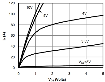
AOD4184 CurveOne important point to take note of is that if an inductive load is being controlled, an external fly-back diode should be used to prevent possible damage when the load is switched off.

The chart to the right from the datasheet shows the effect of the drive (Gate) voltage on the maximum potential current through the MOSFET device.  Since the gate is driven off the load power supply at a 50% level, for a 10V power supply, the current handling will be similar to the 5V curve.

The chart below shows some example temperature measurements of the MOSFET with a load varying from 2.5A to 20A @ 12V.  The logic drive signal varies from 100% duty cycle (always on) to 50% duty cycle or 25% duty cycle.  The measurements are being taken with no airflow over the module and an ambient temperature of 22C.  Since a 12V power supply is being used, the gate voltage is around 6V which gives pretty good performance.

In general, you should keep the MOSFET under about 100°C to keep it happy.  For long-term use, 80°C or lower would be a better target.

Load Amps 12V Input @ 100% duty cycle 12V Input @ 50% duty cycle 12V Input @ 25% duty cycle
2.5A 32°C
5A 39°C 30°C
10A 69°C 47°C
12.5A 102°C 63°C 43°C
15A X 78°C 48°C
20A X 115°C+ 74°C

BEFORE THEY ARE SHIPPED, THESE MODULES ARE:

  • Sample tested per incoming shipment

Notes: 

  1. None

TECHNICAL SPECIFICATIONS

Maximum Ratings
     VDS Drain-Source Voltage 40V max (36V recommended)
     ID Drain Current Max (Continuous) 10A @ 12V
     RDS(on) Drain-Source On-Resistance 8.5mΩ
Dimensions (L x W x H) 35 x 16 x 14mm (1.38 x 0.63 x 0.55″)
Country of Origin China
Datasheet AOD4184
Product Details
RBD-2757
30 Items

Specific References

EAN13
2757
Comments (0)
Grade
No customer reviews for the moment.
16 other products in the same category:

Reference: RBD-2223

MOSFET Electronic Switch DC Controlling Board

(0)
Input Voltage: 3 V ~ 20 V Input Current: 5mA Output Voltage: 5 V ~ 35 V Output Current: 5A Item Dimensions: 46 * 25 * 18mm
BDT 190.00
BDT 190.00 tax incl.
BDT 190.00 tax excl.
BDT 190.00 tax incl.
BDT 0.00 Tax
BDT 190.00 tax excl.
BDT 0.00 Tax
BDT 190.00 tax incl.
More
In-Stock
In stock: 40

Reference: RBD-2226

2 Channel 24V Relay Board Module with OPTO Isolation Support High or Low Level Trigger

(0)
Operating Voltage: 24V DC Two separate LEDs for On/Off indication of the Relay Triggering input voltage 3.3V – 5V 4) Back EMF protection Equipped with high-current relay 10A@250VAC / 10A@30VDC It can control both AC and DC appliances such as Solenoids, Motors, lights, fans, etc High-quality screw terminals (Terminal Block) provided (C, NC, NO) for quick...
BDT 230.00
BDT 230.00 tax incl.
BDT 230.00 tax excl.
BDT 230.00 tax incl.
BDT 0.00 Tax
BDT 230.00 tax excl.
BDT 0.00 Tax
BDT 230.00 tax incl.
More
In-Stock
In stock: 87

Reference: RBD-2091

MY18E20 DS18B20 Compatible Temperature Sensor Module

(0)
Digital signal output 18B20 Temperature Sensor Chip (MY18E20 or DS18b20) Resolution adjustment ranges from 9-12 bytes. Send data via a pin Temperature measurement ranges: -55°C to +125°C, be accurate to 0.5°C.Compatible with DS18B20
BDT 99.00
BDT 99.00 tax incl.
BDT 99.00 tax excl.
BDT 99.00 tax excl.
BDT 99.00 tax incl.
BDT 99.00 tax incl.
BDT 0.00 Tax
BDT 99.00 tax excl.
BDT 99.00 tax excl.
BDT 0.00 Tax
BDT 99.00 tax incl.
More
In-Stock
In stock: 142

Reference: RBD-2921

2.42 inch OLED Screen LCD Display Module 128x64 SSD1309 SPI 7Pin Yellow

(0)
Operating Voltage: 3.3V Resolution: 128 × 64 pixels Communication Interface: SPI (default) Display size: 55.01 × 27.49mm Driver: SSD1309Note: The component, colour & shape of the module may vary depending on our stock rotation.
BDT 1,690.00
BDT 1,690.00 tax incl.
BDT 1,690.00 tax excl.
BDT 1,690.00 tax incl.
BDT 0.00 Tax
BDT 1,690.00 tax excl.
BDT 0.00 Tax
BDT 1,690.00 tax incl.
More
In stock
In stock: 10

Reference: RBD-1575

5V 2 Channel Solid State Relay (SSR)

(0)
Part Number: G3MB-202P Power supply:5VDC/160mA Trigger Voltage (VDC):5 Switching Voltage (VAC):240@2A Isolation: Phototriac
BDT 355.00
BDT 355.00 tax incl.
BDT 355.00 tax excl.
BDT 355.00 tax incl.
BDT 0.00 Tax
BDT 355.00 tax excl.
BDT 0.00 Tax
BDT 355.00 tax incl.
More
In-Stock
In stock: 18

Reference: RBD-0282

XBee USB Adapter

(0)
Specifications: - 3.3V and 5V dual power output- 3.3V and 5V IO compatible- USB2.0 protocol- BitBang mode ready- Easily connected to PC via mini USB cable- Support XBee-setting with software X-CTU
BDT 480.00
BDT 480.00 tax incl.
BDT 480.00 tax excl.
BDT 480.00 tax incl.
BDT 0.00 Tax
BDT 480.00 tax excl.
BDT 0.00 Tax
BDT 480.00 tax incl.
More
In-Stock
In stock: 5

Reference: RBD-0937

Mini Data Logger Module

(0)
SD card interface works with FAT16 or FAT32 formatted cards. 3.3v level shifter circuitry prevents damage to your SD card. Real-time clock (RTC) keeps the time going even when the Arduino is unplugged. The battery backup lasts for years. Included libraries and example code for both SD and RTC mean you can get going quickly Prototyping area for soldering...
BDT 550.00
BDT 550.00 tax incl.
BDT 550.00 tax excl.
BDT 550.00 tax incl.
BDT 0.00 Tax
BDT 550.00 tax excl.
BDT 0.00 Tax
BDT 550.00 tax incl.
More
In-Stock
In stock: 6

Reference: RBD-2542

Brand: DFRobot

SIM808 GSM/GPRS/GPS IoT Board (Arduino Leonardo Compatible)

(0)
This is an SIM808 GSM/GPRS/GPS IoT Board based on Arduino Leonardo. The SIM808 with Leonardo mainboard is the latest development board for multi-purpose applications. The onboard SIM808 module includes an integrated quad-band GSM/GPRS and GPS satellite navigation module, and a 4 layer PCB integrates the microcontroller, microphone, headphone jack and...
BDT 11,290.00
BDT 11,290.00 tax incl.
BDT 11,290.00 tax excl.
BDT 11,290.00 tax incl.
BDT 0.00 Tax
BDT 11,290.00 tax excl.
BDT 0.00 Tax
BDT 11,290.00 tax incl.
More
Last items in stock
In stock: 1

Reference: RBD-2306

WS2812B RGB LED 12 Bit Ring

(0)
The 12 Bit RGB LED Ring Module with Integrated Drivers – WS2812B can be used in colourful curtain-up/ flow water/raindrop/jump flash and so on hundreds of lighting effects. There is a single data line with a very timing-specific protocol. It has trichromatic colour for each pixel and can complete 16,777,216 colours of all true colour displays, the...
BDT 275.00
BDT 275.00 tax incl.
BDT 275.00 tax excl.
BDT 275.00 tax incl.
BDT 0.00 Tax
BDT 275.00 tax excl.
BDT 0.00 Tax
BDT 275.00 tax incl.
More
In stock
In stock: 28

Reference: RBD-1808

STM32 STM32F407VET6 512K System Core Board Development Board

(0)
Model: F407VE-512K STM32F407VET6 development board F407 microcontroller learning board STM32 system board
BDT 4,220.00
BDT 4,220.00 tax incl.
BDT 4,220.00 tax excl.
BDT 4,220.00 tax incl.
BDT 0.00 Tax
BDT 4,220.00 tax excl.
BDT 0.00 Tax
BDT 4,220.00 tax incl.
More
In-Stock
In stock: 5

Reference: RBD-2134

433Mhz Wireless Receiver Learning Code EV1527 Decoding Module 4Ch output With Learning Button

(0)
433Mhz Wireless Receiver Learning Code EV1527 Decoding Module 4-channel output with a learning button Compatible with Arduino/ARM/MCU Ideal for wireless power switch sockets, remote controls, LED lighting, and electric doors Wide range of applications in home automation, security systems, and remote control devices
BDT 490.00
BDT 490.00 tax incl.
BDT 490.00 tax excl.
BDT 490.00 tax incl.
BDT 0.00 Tax
BDT 490.00 tax excl.
BDT 0.00 Tax
BDT 490.00 tax incl.
More
In-Stock
In stock: 20

Reference: RBD-0108

USB Host Shield For Arduino UNO, MEGA, Compatible with Google Android ADK

(0)
Works with standard (dual 5/3.3V) and 3.3V-only (for example, Pro Arduino) boards. Complies with USB Specification Revision 2.0 (Full-Speed 12Mbps Peripheral, Full-/Low-Speed 12Mbps/1.5Mbps Host) Supports HID devices, such as keyboards, mice, joysticks, etc. Compatible with Mass storage devices, such as USB sticks, memory card readers, external hard...
BDT 1,199.00
BDT 1,199.00 tax incl.
BDT 1,199.00 tax excl.
BDT 1,199.00 tax incl.
BDT 0.00 Tax
BDT 1,199.00 tax excl.
BDT 0.00 Tax
BDT 1,199.00 tax incl.
More
In-Stock
In stock: 12

Reference: RBD-1809

Digispark Pro - ATtiny167 with Micro USB

(0)
Digispark Pro  ATtiny167  Micro USB 16MHz
BDT 539.00 BDT 549.00
BDT 549.00 BDT 539.00 tax incl.
BDT 549.00 BDT 539.00 tax excl.
BDT 549.00 BDT 539.00 tax incl.
BDT 0.00 BDT 0.00 Tax
BDT 549.00 BDT 539.00 tax excl.
BDT 0.00 BDT 0.00 Tax
BDT 549.00 BDT 539.00 tax incl.
More
In-Stock
In stock: 29

Reference: RBD-1603

MicroPython Board R3 ATmega328P+ESP8266, 8Mb flash, USB-TTL CH340G, Micro-USB

(0)
USB-TTL converter. Logic Level: 5V. Operating Supply Voltage: 5V. Digital I/O Pins: 14. Analog I/O Pins: 6.
BDT 1,199.00
BDT 1,199.00 tax incl.
BDT 1,199.00 tax excl.
BDT 1,199.00 tax incl.
BDT 0.00 Tax
BDT 1,199.00 tax excl.
BDT 0.00 Tax
BDT 1,199.00 tax incl.
More
In-Stock
In stock: 32

Follow us on Facebook