- Out-of-Stock

Banner


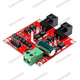
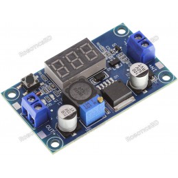
The 250W 8A Buck Converter XH-M404 Adjustable DC-DC Step-Down Module with XL4016 IC is a powerful and reliable solution for voltage regulation in electronics, robotics, and DIY power systems. It allows you to step down a higher DC input voltage (5V–40V) to an adjustable output range of 1.25V–36V, making it ideal for powering various devices and circuits. With continuous current support up to 5A and peak bursts up to 8A, this module ensures stable operation even under heavy loads. The integrated green digital voltmeter makes it easy to monitor the output voltage in real time, while built-in overcurrent protection and thermal shutdown features enhance safety and durability. Its compact design with mounting holes ensures flexibility in installation, making it a practical choice for hobbyists and professionals alike.. Featured By RoboticsBD.
Product Images are shown for illustrative purposes only and may differ from the actual product.
RoboticsBD RoboticsBD RoboticsBD RoboticsBD RoboticsBD RoboticsBD RoboticsBD RoboticsBD RoboticsBD RoboticsBD
High Power Output: Supports up to 250W with a peak current of 8A.
Wide Voltage Range: Input 5V–40V, adjustable output 1.25V–36V.
Real-Time Monitoring: Built-in green digital voltmeter for output display.
Safety Features: Overcurrent limiting and thermal shutdown protection.
Durable Build: XL4016 IC ensures stability and efficiency in conversion.
Easy Installation: Compact PCB with mounting holes for secure setup.
RoboticsBD RoboticsBD RoboticsBD RoboticsBD RoboticsBD RoboticsBD RoboticsBD RoboticsBD RoboticsBD RoboticsBD
Powering Arduino, Raspberry Pi, and other development boards.
Voltage regulation for robotics and embedded systems.
DIY adjustable power supplies for electronics projects.
Battery charging and step-down voltage control.
LED strips, motor drivers, and other DC load applications.
RoboticsBD RoboticsBD RoboticsBD RoboticsBD RoboticsBD RoboticsBD RoboticsBD RoboticsBD RoboticsBD RoboticsBD
| Model | XH-M404 (XL4016 IC) |
| Input Voltage Range | 5V – 40V |
| Output Voltage Range | 1.25V – 36V |
| Continuous Output Current | Up to 5A |
| Peak Output Current | Up to 8A |
| Maximum Power Output | 250W (120W continuous typical) |
| Built-in Display | Green Digital Voltmeter |
| Protections | Overcurrent, Thermal Shutdown |
| Mounting Holes | Yes, 4 (corner mounting) |
| Dimensions | 7 × 5 × 3 cm |
| Shipment Weight | 0.0682 kg |
| Shipment Dimensions | 7 × 5 × 3 cm |
Please allow 5% measuring deviation due to manual measurement.
RoboticsBD RoboticsBD RoboticsBD RoboticsBD RoboticsBD RoboticsBD RoboticsBD RoboticsBD RoboticsBD RoboticsBD
The built-in green voltmeter display shows the output voltage.
The display has a stated accuracy of ± 0.1V. There is a small potentiometer on the back of the module that can be used to calibrate the display against a reference voltmeter if desired.
RoboticsBD RoboticsBD RoboticsBD RoboticsBD RoboticsBD RoboticsBD RoboticsBD RoboticsBD RoboticsBD RoboticsBD
The module has a multi-turn potentiometer for adjustment of the output voltage.
Turning the pot CW increases the output voltage while turning it CCW decreases the output voltage.
The lowest output voltage is approximately 1.25V. The upper limit of the adjustment range will depend on the input voltage and is typically about 1.5V less than the input voltage. With a 12V input for instance, the upper output limit will be approximately 10.5V.
RoboticsBD RoboticsBD RoboticsBD RoboticsBD RoboticsBD RoboticsBD RoboticsBD RoboticsBD RoboticsBD RoboticsBD
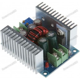
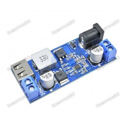
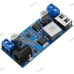
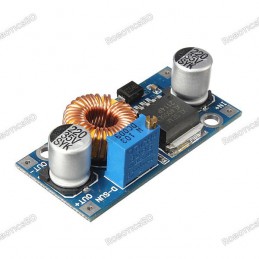
These are compact boards with input power applied to one end and output power available on the other end, unfortunately with no clear markings unless you read Chinese.
With the LED display facing towards you, the input is on the left and the output is on the right. The connections are made using screw terminals for easy connection to wires for hookup.
The minimum recommend input voltage is 5V. With a 5V input, the LED display will dim, but the converter will continue to operate OK. At 6V input, the display will be at full brightness.
The input has a reverse polarity protection diode.
Input Power Terminals (Left Side)
‘+’ = Input voltage (5 to 40V)
‘-‘ = Ground
RoboticsBD RoboticsBD RoboticsBD RoboticsBD RoboticsBD RoboticsBD RoboticsBD RoboticsBD RoboticsBD RoboticsBD
Output power is available on the right side of the module. It also uses screw terminals for easy connection to wire for hookup.
Output Power Terminals (Right Side)
‘+’ = Output voltage (1.25 to 36V)
‘-‘ = Ground
RoboticsBD RoboticsBD RoboticsBD RoboticsBD RoboticsBD RoboticsBD RoboticsBD RoboticsBD RoboticsBD RoboticsBD
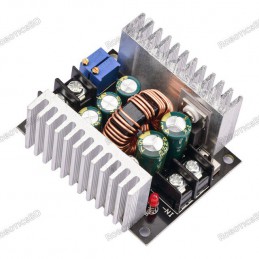
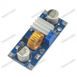
This DC-DC Converter is built with some heavy duty parts which is nice to see.
Heat sinks are large and finned with good thermal coupling and they are also electrically isolated. Because of the large heat sinks, force air cooling if utilized is very effective and can easily decrease temps by 30°C or more.
The inductor utilizes heavy-duty wire that can handle the rated current. The Schottky diode is a massive MBR20100C dual 10A unit which is also mounted to a large heat sink.
We have pushed 10A though the device with some fan cooling to test limits, however the chip is only rated up to 8A, so even with fan cooling, more than 8A should not be pulled from the module. For long-term use, 5A is a good upper limit depending on the input / output voltage settings and assuming no fan cooling. With fan cooling, 8A is supported in many of the modes.
The table below gives some thermal results with an ambient temp of approx 25°C and no fan cooling. We tested at 5A and in some cases then tested at 8A or the upper current limit where we were getting close to a thermal shutdown. With forced air cooling, the temperatures dropped by about 30°C on average when under higher loads.
RoboticsBD RoboticsBD RoboticsBD RoboticsBD RoboticsBD RoboticsBD RoboticsBD RoboticsBD RoboticsBD RoboticsBD
This module delivers reliable performance across a wide input range, with output efficiency typically between 68% and 96% depending on voltage and load conditions. At lower voltage differences, it maintains higher current output and efficiency, while larger input-to-output drops reduce efficiency and increase IC temperature. For example, with 24V input to 5V output at 120A, efficiency peaks at 96%, whereas with 32V input to 3.3V output, efficiency drops to around 68%. Thermal performance is stable, generally keeping the IC below 90°C under most loads. Ripple is typically ~100mV peak-to-peak, with noise spikes averaging 150–400mV, which remains acceptable for most applications. The scope capture confirms low and consistent ripple/noise across varying loads, ensuring dependable operation.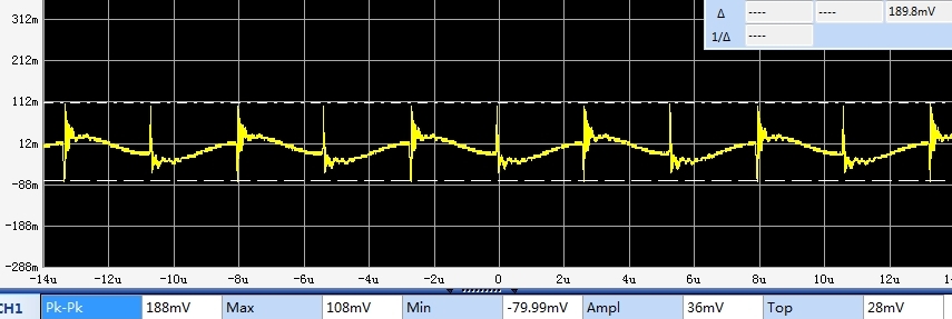
RoboticsBD RoboticsBD RoboticsBD RoboticsBD RoboticsBD RoboticsBD RoboticsBD RoboticsBD RoboticsBD RoboticsBD
1 x 250W 8A Buck Converter XH-M404 Adjustable DC-DC Step-Down Module XL4016
RoboticsBD RoboticsBD RoboticsBD RoboticsBD RoboticsBD RoboticsBD RoboticsBD RoboticsBD RoboticsBD RoboticsBD
RoboticsBD RoboticsBD RoboticsBD RoboticsBD RoboticsBD RoboticsBD RoboticsBD RoboticsBD RoboticsBD RoboticsBD
Specific References
Your review appreciation cannot be sent
Report comment
Report sent
Your report cannot be sent
Write your review
Review sent
Your review cannot be sent
Reference: RBD-2227
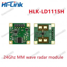
Brand: Hi-Link
Reference: RBD-2428
Reference: RBD-2728
Reference: RBD-2099
Reference: RBD-2426
Reference: RBD-0924
Reference: RBD-2094
Reference: RBD-2093
Reference: RBD-2083
Reference: RBD-2542
Brand: DFRobot
We'll slide into your inbox when the product is back in stock.
Reference: RBD-2226
Reference: RBD-2095
Reference: RBD-2091
Reference: RBD-2097
Reference: RBD-2682
Reference: RBD-1910
Reference: 0245
Reference: RBD-1524
Reference: RBD-2615
Reference: RBD-2686
Reference: RBD-0842
Reference: RBD-1360
Reference: RBD-2272
Reference: RBD-2640
Reference: RBD-1524
Reference: RBD-2222
Reference: RBD-0395
check_circle
check_circle