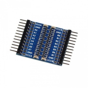
The PCF8574 I2C I/O Expansion Module is a versatile solution for projects requiring additional digital I/O beyond what microcontrollers natively support. With 8 quasi-bidirectional data lines, this module connects via the I2C bus, requiring only two MCU pins while providing flexible expansion up to 64 I/O lines (or 128 when combined with PCF8574A variants). It features jumper-configurable addresses (0x20–0x27) and supports both 3.3V and 5V systems, making it compatible with a wide range of MCUs like Arduino, ESP32, and STM32. With interrupt capability for state changes and up to 25mA sink current per pin, the PCF8574 is ideal for driving LEDs, reading pushbuttons, or interfacing with other digital components in embedded and automation projects. Featured By RoboticsBD.
Product Images are shown for illustrative purposes only and may differ from the actual product.
RoboticsBD RoboticsBD RoboticsBD RoboticsBD RoboticsBD RoboticsBD RoboticsBD RoboticsBD RoboticsBD RoboticsBD
Features:
Provides 8 additional quasi-bidirectional I/O lines.
Expandable up to 64 lines (8 modules) or 128 lines (with PCF8574A).
I2C interface with base address 0x20 and jumper-adjustable range up to 0x27.
3.3V and 5V compatible, supporting a wide variety of MCUs.
Interrupt output pin for real-time input monitoring.
Strong 25mA sink current for driving LEDs or digital loads.
Simple daisy-chain expansion with loop-thru feature.
Compact module with labeled pins for easy wiring.
RoboticsBD RoboticsBD RoboticsBD RoboticsBD RoboticsBD RoboticsBD RoboticsBD RoboticsBD RoboticsBD RoboticsBD
Applications:
Expanding digital I/O on Arduino, ESP32, or STM32 boards.
Driving LEDs and low-current digital devices.
Interfacing with pushbuttons, switches, and input sensors.
Creating large input/output matrices for automation.
Use in robotics, home automation, and embedded projects requiring multiple I/O.
RoboticsBD RoboticsBD RoboticsBD RoboticsBD RoboticsBD RoboticsBD RoboticsBD RoboticsBD RoboticsBD RoboticsBD
| General Specifications |
| Product Type | I2C I/O Expansion Module |
| IC Used | PCF8574 |
| I/O Lines | 8 (expandable up to 64 / 128 with PCF8574A) |
| Interface | I2C (addresses 0x20–0x27) |
| Voltage Compatibility | 3.3V / 5V |
| Sink Current per Pin | Up to 25mA |
| Source Current per Pin | ~300uA (weak pull-up) |
| Interrupt Output | Yes (active LOW, open drain) |
| Address Configuration | Jumpers A0–A2 |
| Expansion Capability | Loop-thru for daisy chaining |
| Shipment Weight | 0.0055 kg |
| Shipment Dimensions | 6 × 2 × 2 cm |
Please allow 5% measuring deviation due to manual measurement.
RoboticsBD RoboticsBD RoboticsBD RoboticsBD RoboticsBD RoboticsBD RoboticsBD RoboticsBD RoboticsBD RoboticsBD
Documentation:
I2C Interface
The module has an easy to use I2C interface that can be configured to use any one of eight different I2C addresses if you want to use multiple modules in the same system or if you run into an address conflict with another device.PCF8574 I2C IO Expansion Module - Jumpers
The base I2C address of the modules is 0x20.
There are three address jumps (A0-A2) the determines which I2C address to use. As shipped, these jumpers are all set to the ‘-‘ side which is ground or LOW as shown in the picture. The ‘+’ side is Vcc or HIGH.
This puts the module at the base address of 0x20. The jumpers can be moved in a binary fashion to increase the address, so the address can range from 0x20 to 0x27 as shown in the table below.
If you daisy-chain the modules, you will need to set a different address for each of the modules.
| Address (Hex) | A2 | A1 | A0 |
| 0x20 | LOW | LOW | LOW |
| 0x21 | LOW | LOW | HIGH |
| 0x22 | LOW | HIGH | LOW |
| 0x23 | LOW | HIGH | HIGH |
| 0x24 | HIGH | LOW | LOW |
| 0x25 | HIGH | LOW | HIGH |
| 0x26 | HIGH | HIGH | LOW |
| 0x27 | HIGH | HIGH | HIGH |
You may run into devices with the PCF8574A part installed. If that happens, don’t panic. These just use a different starting I2C address of 0x38. This part is offered by the mfr so that if both A and non-A parts are used together in a system, the number of modules can be increased up to a maximum of 16 providing at total of 128 digital lines. The ‘T‘ marking on the devices just denote that it is a surface mount device.
If there is ever a doubt about the I2C address of this or any device, just hook it up to the I2C bus and apply power and ground and then run the I2C scanner software.

RoboticsBD RoboticsBD RoboticsBD RoboticsBD RoboticsBD RoboticsBD RoboticsBD RoboticsBD RoboticsBD RoboticsBD
I/O Functionality
The I/O is defined as quasi-bidirectional. A quasi-bidirectional I/O is either an input or output port without using a direction control register. When set as inputs, the pins act as normal inputs do. When set as outputs, the PCF8574 device drives the outputs LOW with up to 25mA sink capability but when driving the outputs HIGH, they are just pulled up high with a weak internal pull-up. That enables an external device to overpower the pin and drive it LOW.
The device powers up with the 8 data lines all set as inputs.
When using the pins as inputs, the pins are set to HIGH by the MCU, which turns on a weak 100 uA internal pull-up to Vcc. They will read as HIGH if there is no input or if the pin is being driven HIGH by an external signal but can be driven LOW by an external signal that can easily override the weak pull-up.
If used as outputs, they can be driven LOW by the MCU by writing a LOW to that pin. A strong pull-down is turned on and stays on to keep the pin pulled LOW. If the pin is driven HIGH by the MCU, a strong pull-up is turned on for a short time to quickly pull the pin HIGH and then the weak 100uA pull-up is turned back on to keep the pin HIGH.
If the pins are set to be outputs and are driven LOW, it is important that an external signal does not also try to drive it HIGH or excessive current may flow and damage the part.
Whenever the internal register is read, the value returned depends on the actual voltage or status of the pin.
The I/O ports are entirely independent of each other, but they are controlled by the same read or write data byte.
RoboticsBD RoboticsBD RoboticsBD RoboticsBD RoboticsBD RoboticsBD RoboticsBD RoboticsBD RoboticsBD RoboticsBD
Interrupt Output
The interrupt open drain output pin is active LOW. It is normally pulled HIGH using a pull-up resistor and is driven low by the PCF8574 when any of the inputs change state. This signals the MCU to poll the part to see what is going on. If connecting this pin, enable the internal pull-up resistor on the MCU or add an external pull-up of 10K or so.
If using interrupts with multiple modules, since they are open drain they can be tied together if a single interrupt back to the MCU is desired.
RoboticsBD RoboticsBD RoboticsBD RoboticsBD RoboticsBD RoboticsBD RoboticsBD RoboticsBD RoboticsBD RoboticsBD
Module Connections
The connections to the module are straight forward.
- Supply 3.3 or 5V power and ground.
- Connect I2C SCL and SDA lines to same on the MCU.
- If used, connect the INT line to an interrupt input on the MCU and use a pull-up resistor.
1 x 4 Header (Male & Female)
- VCC = Vcc (2.5V – 6V) typically connects to uC 3.3V or 5V
- GND = Ground connects to uC ground
- SDA = I2C SDA connects to uC I2C SDA
- SCL = I2C SCL connects to uC I2C SCL
1 x 9 Header
- P0 = I/O Pin 0
- P1 = I/O Pin 1
- P2 = I/O Pin 2
- P3 = I/O Pin 3
- P4 = I/O Pin 4
- P5 = I/O Pin 5
- P6 = I/O Pin 6
- P7 = I/O Pin 7
- INT = Interrupt Output – connects to MCU interrupt pin. Active LOW
RoboticsBD RoboticsBD RoboticsBD RoboticsBD RoboticsBD RoboticsBD RoboticsBD RoboticsBD RoboticsBD RoboticsBD
OUR EVALUATION RESULTS:
These modules are useful for expanding digital I/O.
One thing to keep in mind is that since the device has strong drive (25mA) when sinking current, but low drive (300uA) when sourcing current, it is best to drive LEDs and similar devices that require higher current by tying their anode to Vcc and pulling their cathode LOW with the PCF8574. A current limiting resistor is generally required.
The example program below sets up all 8 lines as inputs and writes a HIGH to them to enable the weak internal pullups of the PCF8574, so these pins will read HIGH unless something drives them low.
Pushbuttons with one side grounded can be connected to these inputs. The MCU which then scans the PCF8574 inputs and prints out any button found to be pressed.
- SDA / SCL lines should be connected to same on MCU.
- Ground and 3.3V or 5V power should be applied to match the MCU power
- Hook up one or more pushbuttons to one or more of the inputs or can just ground pins with a jumper wire for testing.
The example here uses the xreef/pcf8574 library that can be downloaded from GitHub: https://github.com/xreef/PCF8574_library
RoboticsBD RoboticsBD RoboticsBD RoboticsBD RoboticsBD RoboticsBD RoboticsBD RoboticsBD RoboticsBD RoboticsBD
PCF8574 Module Test Program
/*
   This example for the PCF8574 takes pushbutton inputs on pins 0-7 and
   sends the number of the button pressed to the Serial Monitor window.
   Pins are normally HIGH and pulled LOW when button is pressed.

   Uses the xreef/PCF8574.h library
*/
#include "Arduino.h"
#include "PCF8574.h"

PCF8574 pcf8574(0x20);  // Set (I2C address)

//===============================================================================
//  Initialization
//===============================================================================
void setup()
{
 Serial.begin(9600);

 for(int i=0;i<8;i++) {
    pcf8574.pinMode(i, INPUT);    // Set all pins as inputs
    pcf8574.digitalWrite(i,HIGH); // Enable weak pull-ups to pull pins HIGH
  }
  pcf8574.begin();
  delay(500);  // Give the pcf8574 a little time to initialize
}
//===============================================================================
//  Main
//===============================================================================
void loop()
{ // just loop scanning the keys
   if (pcf8574.digitalRead(P0)==LOW) {Serial.println("KEY 0");}
   if (pcf8574.digitalRead(P1)==LOW) {Serial.println("KEY 1");}
   if (pcf8574.digitalRead(P2)==LOW) {Serial.println("KEY 2");}
   if (pcf8574.digitalRead(P3)==LOW) {Serial.println("KEY 3");}
   if (pcf8574.digitalRead(P4)==LOW) {Serial.println("KEY 4");}
   if (pcf8574.digitalRead(P5)==LOW) {Serial.println("KEY 5");}
   if (pcf8574.digitalRead(P6)==LOW) {Serial.println("KEY 6");}
   if (pcf8574.digitalRead(P7)==LOW) {Serial.println("KEY 7");}
   delay(250);
}
RoboticsBD RoboticsBD RoboticsBD RoboticsBD RoboticsBD RoboticsBD RoboticsBD RoboticsBD RoboticsBD RoboticsBD
Package Includes:
1 x PCF8574 I2C I/O Expansion Module
RoboticsBD RoboticsBD RoboticsBD RoboticsBD RoboticsBD RoboticsBD RoboticsBD RoboticsBD RoboticsBD RoboticsBD
RoboticsBD RoboticsBD RoboticsBD RoboticsBD RoboticsBD RoboticsBD RoboticsBD RoboticsBD RoboticsBD RoboticsBD