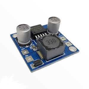
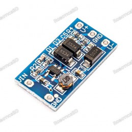
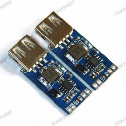
The AMS1117 5V to 3.3V Step-Down Regulator Module is a compact and reliable solution for powering 3.3V devices from a 5V supply. Based on the AMS1117-3.3 regulator, it delivers up to 800mA output current, with 500–600mA recommended for stable operation. This module features built-in short circuit and thermal protection, ensuring safety under load conditions, and includes a red power LED for quick status indication. While optimized for 5V input, it can also accept higher voltages, though current capacity must be derated as voltage increases. Its small footprint and breadboard-friendly design make it an excellent choice for powering sensors, logic ICs, ESP8266/ESP32 boards, and other 3.3V components in DIY electronics and embedded projects. Featured By RoboticsBD.
Product Images are shown for illustrative purposes only and may differ from the actual product.
RoboticsBD RoboticsBD RoboticsBD RoboticsBD RoboticsBD RoboticsBD RoboticsBD RoboticsBD RoboticsBD RoboticsBD
Features:
Converts 5V input to regulated 3.3V output.
Supports up to 800mA (500–600mA recommended).
Built-in short circuit and thermal protection.
Compact, breadboard-friendly design.
Onboard red LED indicates power status.
Usable with higher input voltages, with current derating.
RoboticsBD RoboticsBD RoboticsBD RoboticsBD RoboticsBD RoboticsBD RoboticsBD RoboticsBD RoboticsBD RoboticsBD
Applications:
Powering 3.3V logic devices and microcontrollers.
Supplying voltage for ESP8266, ESP32, and similar Wi-Fi modules.
Sensor modules requiring stable 3.3V supply.
DIY electronics and prototyping on breadboards.
Educational and embedded circuit projects.
RoboticsBD RoboticsBD RoboticsBD RoboticsBD RoboticsBD RoboticsBD RoboticsBD RoboticsBD RoboticsBD RoboticsBD
| General Specifications |
| Product Type | Step-Down Regulator Module |
| Model | AMS1117-3.3 |
| Input Voltage | 5V (usable up to 12V with derating) |
| Output Voltage | 3.3V |
| Max Rated Current | 800mA |
| Recommended Current | 500–600mA |
| Protections | Short circuit, thermal shutdown |
| LED Indicator | Yes (red) |
| Efficiency | Dependent on Vin – Vout difference |
| Footprint | Compact, breadboard-friendly |
| Shipment Weight | 0.0001 kg |
| Shipment Dimensions | 2 × 2 × 2 cm |
Please allow 5% measuring deviation due to manual measurement.
RoboticsBD RoboticsBD RoboticsBD RoboticsBD RoboticsBD RoboticsBD RoboticsBD RoboticsBD RoboticsBD RoboticsBD
Documentation:
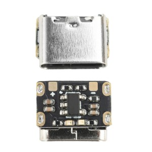
Module Connections
There is a 3-pin right angle header for making connections.
1 x 3 Header
- VIN = Connect to 5V
- OUT = 3.3V Output
- GND = Connect to ground
RoboticsBD RoboticsBD RoboticsBD RoboticsBD RoboticsBD RoboticsBD RoboticsBD RoboticsBD RoboticsBD RoboticsBD
OUR EVALUATION RESULTS:
These are nice little modules that make it easy to have a source of 3.3V for a project.
While the chip is rated for 800 mA with a 5V input, the tiny module does not have enough heat sinking to hit that number for long. In our testing, after about 5 minutes at 800 mA the device safely went into thermal shutdown. At 700 mA, it got hot (120C on tab) but kept chugging along OK. Probably best to consider it a 500-600 mA max device.
It is possible to use a higher input voltage than 5V, but as with any linear regulator, the power dissipation of the regulator is dependent on the difference between the input voltage and the output voltage along with the amount of current that is being drawn from the regulator.
The larger the difference between the Vin and Vout, the higher the power dissipation which limits how much current can be drawn from the device. As you can see in the chart below, the usable current goes down rapidly as the input voltage increases. These are best suited for 5V operation unless your current requirements are small. At 9V current should be limited to about 200 mA and at 12V the current should be limited to about 75 mA
RoboticsBD RoboticsBD RoboticsBD RoboticsBD RoboticsBD RoboticsBD RoboticsBD RoboticsBD RoboticsBD RoboticsBD
Output Current vs Input Voltage
| V In | V Out | Tab Temp | Current (ambient 22C) |
| 5V | 3.3V | 120C | 700A |
| 5V | 3.3V | 105C | 600A |
| 5V | 3.3V | 95C | 500A |
| 9V | 3.3V | 95C | 200mA |
| 12V | 3.3V | 98C | 75mA
|
One thing to be aware of whenever using any breadboard friendly power module is that while the module may be able to handle 500+mA, the typical breadboard jumper wires will have a fairly significant voltage loss passing that much current on both the input and output sides of the module. This is most important on the output side, since we are trying to lose some of the voltage on the input side anyway.
When using with higher current loads you may need to double-up on the wires or use heavier gauge wires on both the input and output voltage connections to minimize the voltage drop.
RoboticsBD RoboticsBD RoboticsBD RoboticsBD RoboticsBD RoboticsBD RoboticsBD RoboticsBD RoboticsBD RoboticsBD
Package Includes:
1 x AMS1117 5V to 3.3V Step-Down Regulator Module
RoboticsBD RoboticsBD RoboticsBD RoboticsBD RoboticsBD RoboticsBD RoboticsBD RoboticsBD RoboticsBD RoboticsBD
RoboticsBD RoboticsBD RoboticsBD RoboticsBD RoboticsBD RoboticsBD RoboticsBD RoboticsBD RoboticsBD RoboticsBD