ESP32-C6-WROOM-1 and ESP32-C6-WROOM-1U are general-purpose modules supporting Wi-Fi 6 in 2.4 GHz band, Bluetooth 5, and IEEE 802.15.4 (Zigbee 3.0 and Thread 1.3). They are built around the ESP32-C6 chip, and comes with a 8 MB SPI flash. ESP32-C6-WROOM-1 uses on-board PCB antenna, whereas ESP32-C6-WROOM-1U uses external antenna connector. For more information, see ESP32-C6-WROOM-1 Datasheet.
This section provides a brief introduction of ESP32-C6-DevKitC-1, instructions on how to do the initial hardware setup and how to flash firmware onto it.
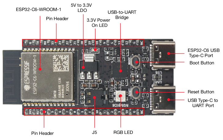
The key components of the board are described in a clockwise direction.
Key Component
Description
ESP32-C6-WROOM-1 or ESP32-C6-WROOM-1U
ESP32-C6-WROOM-1 and ESP32-C6-WROOM-1U are general-purpose modules supporting Wi-Fi 6 in 2.4 GHz band, Bluetooth 5, and IEEE 802.15.4 (Zigbee 3.0 and Thread 1.3). They are built around the ESP32-C6 chip, and comes with a 8 MB SPI flash. ESP32-C6-WROOM-1 uses on-board PCB antenna, whereas ESP32-C6-WROOM-1U uses external antenna connector. For more information, see ESP32-C6-WROOM-1 Datasheet.
Pin Header
All available GPIO pins (except for the SPI bus for flash) are broken out to the pin headers on the board.
5 V to 3.3 V LDO
Power regulator that converts a 5 V supply into a 3.3 V output.
3.3 V Power On LED
Turns on when the USB power is connected to the board.
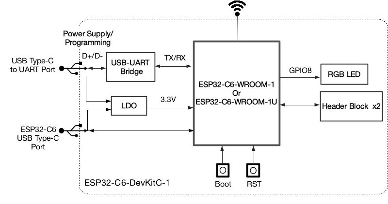
USB-to-UART Bridge
Single USB-to-UART bridge chip provides transfer rates up to 3 Mbps.
ESP32-C6 USB Type-C Port
The USB Type-C port on the ESP32-C6 chip compliant with USB 2.0 full speed. It is capable of up to 12 Mbps transfer speed (Note that this port does not support the faster 480 Mbps high-speed transfer mode). This port is used for power supply to the board, for flashing applications to the chip, for communication with the chip using USB protocols, as well as for JTAG debugging.
Boot Button
Download button. Holding down Boot and then pressing Reset initiates Firmware Download mode for downloading firmware through the serial port.
Reset Button
Press this button to restart the system.
USB Type-C to UART Port
Used for power supply to the board, for flashing applications to the chip, as well as the communication with the ESP32-C6 chip via the on-board USB-to-UART bridge.
Be sure to use a good quality USB cable. Some cables are for charging only and do not provide the needed data lines nor work for programming the boards.
Please proceed to ESP-IDF Get Started, which will quickly help you set up the development environment then flash an application example onto your board.
If you order a few samples, each ESP32-C6-DevKitC-1 comes in an individual package in either antistatic bag or any packaging depending on your retailer.
The J5 headers on ESP32-C6-DevKitC-1 (see J5 in Figure ESP32-C6-DevKitC-1 - front) can be used for measuring the current drawn by the ESP32-C6-WROOM-1(U) module:
Remove the jumper: Power supply between the module and peripherals on the board is cut off. To measure the module’s current, connect the board with an ammeter via J5 headers.
Apply the jumper (factory default): Restore the board’s normal functionality.
Note
When using 3V3 and GND pin headers to power the board, please remove the J5 jumper, and connect an ammeter in series to the external circuit to measure the module’s current.
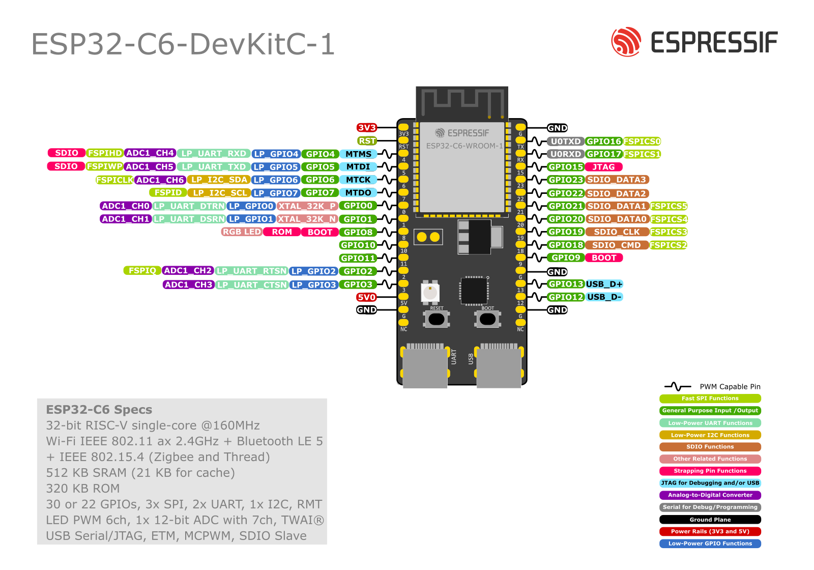
The two tables below provide the Name and Function of the pin headers on both sides of the board (J1 and J3). The pin header names are shown in Figure ESP32-C6-DevKitC-1 - front. The numbering is the same as in the ESP32-C6-DevKitC-1 Schematic (PDF).
MTMS, MTDI, GPIO8, GPIO9, and GPIO15 are strapping pins of the ESP32-C6 chip. These pins are used to control several chip functions depending on binary voltage values applied to the pins during chip power-up or system reset. For description and application of the strapping pins, please refer to ESP32-C6 Datasheet > Section Strapping Pins.
For boards with the PW number of and after PW-2023-02-0139 (on and after February 2023), J5 is changed from straight headers to curved headers.
For boards with the PW number of and after PW-2023-07-XXXX (on and after July 2023), multi-point calibration is performed on ADC instead of two-point calibration, and the measurement range and accuracy are illustrated in ESP32-C6 Datasheet > Section ADC Characteristics. For boards with eariler PW number, please ask our sales team to provide the actual range and accuracy according to batch.
For boards with the PW number of and after PW-2023-07-0440 (on and after July 2023), to optimize the WS2812 driving circuit, the resistance of R29 is updated from 4.7 kΩ to 10 kΩ, and the resistance of R6 is updated from 10 kΩ to 3.3 kΩ. For details, see
Flash LED off: 180mA @ 5V.
Flash LED on to maximum brightness: 310mA @ 5V.
Deep-sleep: 6mA @ 5V min.
Modem-sleep: 20mA @ 5V min.
Light-sleep: 6.7mA @ 5V min.
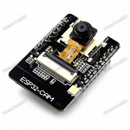
Programmer: ESP32-CAM-MB MICRO USB Download Module
The ESP32 CAM does not come pre-assembled with the camera. You'll need to connect the camera ribbon cable to the board, a task which can be...
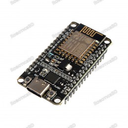
The Development Kit based on ESP8266, integrates GPIO, PWM, IIC, 1-Wire and ADC all in one board. Power your development in the fastest way combine with NodeMCU Firmware! R2 version had CP2102 USB-TTL instead, larger current support, slim board can put on breadboard. Programing it with Arduino IDE.
A high-quality USB cable is essential for this board to...
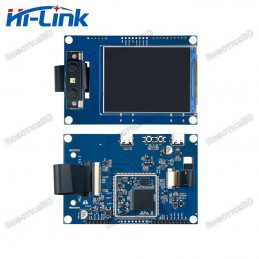
HLK-TX510 is a module developed based on artificial intelligence chip TX510, AI computing power 1.2T@8bit/9.6T@binary, supports mixed precision, can quickly detect faces, supports 3D living detection, 3D face recognition, infrared living detection, Visible light live detection, etc., can resist two-dimensional attacks such as photos and videos, and...
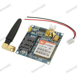
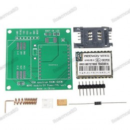
This module is intended for advanced users who require moderate knowledge of GSM systems and microcontrollers. It needs wiring and firmware updates to unlock the country lock.
Dual-Band 900/ 1800 MHz
GPRS multi-slot class 10/8GPRS mobile station class B
Compliant to GSM phase 2/2+
Dimensions: 24*24*3 mm
Weight: 3.4g
Control via AT commands (GSM 07.07...
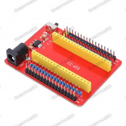
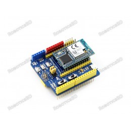
ESP32-IO shield
Compatible with RoboticsBD ESP32 Core board
Brings out all the pins of RoboticsBD ESP32 Core board
2 rows of 2.54mm pin headers for connecting other sensors
Power supply circuit for RoboticsBD ESP32 Core board
DC 7-12V voltage input
DIP switch for controlling the power
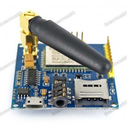
Working frequency: quad-band network, 850 / 900 / 1800 / 1900MHz
Working voltage: 4.8-9VDC(On-board voltage regulator circuit supply power for A6 module)
Working Current: maximum of 2A. RoboticsBD
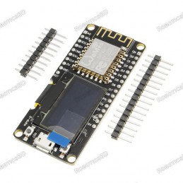
Integrated 0.96″ OLED
Micro USB connection
Compatible with Arduino
Compatible with NodeMCU(Lua for ESP8266)
Input Power 5V
Compatible for Arduino
Compatible with NodeMCU(Lua for ESP8266)A high-quality USB cable is essential for this board to ensure sufficient current supply; otherwise, your board may not be recognized by the Windows Device Manager. Please...
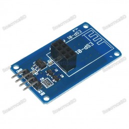
On-board level shift circuit
Arduino UNO R3 and the compatible board can directly connect to this module;
Interface logic voltage: 3.3V / 5V compatible(On-board level shift circuit);
Working voltage: 4.5~5.5V (Onboard 3.3V LDO Regulator);
Working current: 240mA(MAX).RoboticsBD
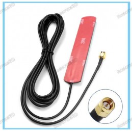
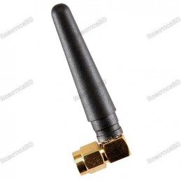
Product: GSM Antenna
Color: Black
SMA male straight 5cm 900-1800MHz radio antenna.
Frequency: 900MHz – 1800MHz
Maximum Power: 50W
Length: 5cm/1.97 inch
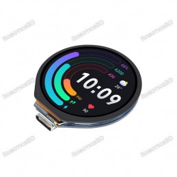
New Rainproof WIFI Transmitter Wireless P2P 30fps realtime video FPV Transfer compatible IPhone, IPad, Android system
WiFi transmission, no need router, no need internet.
Support iPhone, iPad, and Android phone
Transmission distance with no obstacle 150meters
The terminal shall support Android 2.2 or above, and iOS shall support Version 4.3 or above.
Easy...
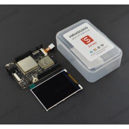
Based on K210 RISC-V AI processor, the Maixduino AI development board comes with MI AI module and ESP32 module for WiFi and Bluetooth connectivity in the Arduino UNO form factor.
K210 comes with a dual-core processor chip with independent FPU, 64 bits CPU bit width, 8 MB on-chip SRAM, 400 adjustable nominal frequency, and double-precision FPU supporting...
ESP32-C6-WROOM-1 and ESP32-C6-WROOM-1U are general-purpose modules supporting Wi-Fi 6 in 2.4 GHz band, Bluetooth 5, and IEEE 802.15.4 (Zigbee 3.0 and Thread 1.3). They are built around the ESP32-C6 chip, and comes with a 8 MB SPI flash. ESP32-C6-WROOM-1 uses on-board PCB antenna, whereas ESP32-C6-WROOM-1U uses external antenna connector. For more information, see ESP32-C6-WROOM-1 Datasheet.