DESCRIPTION
The TEMT6000 Ambient Light Sensor Module is a visible light to analog voltage converter for measuring the intensity of light.
PACKAGE INCLUDES:
- TEMT6000 Ambient Light Sensor Module
- Male header
KEY FEATURES OF TEMT6000 AMBIENT LIGHT SENSOR MODULE:
- Visible light sensitivity with peak at 570nm
- +/- 60 degree angle of sensitivity
- Fast reacting in uSec range.
- Analog voltage output proportional to the intensity of light falling on the detector
- 3.3 and 5V compatible
The TEMT6000 was designed as an ambient light detector for automatically controlling the backlight dimming of cell phones, laptops, car dashboards and similar items. It can be used in many applications where it is desirable to measure the relative brightness of the light falling on the sensor.
The sensor is designed to mainly detect the light spectrum visible to the human eye with peak sensitivity at 570nm which is in the green spectrum. The full range spans 440nm to 800nm.
The sensor itself is a NPN phototransistor. Increased light intensity on the base of the transistor increases the current flowing through the transistor collector/emitter.
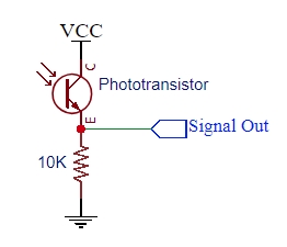
Schematic of TEMT6000 Module
The module includes a 10K resistor. The TEMT6000 sensor and the resistor form a voltage divider network as shown to the right. As light intensity increases, the current flow also increases. This causes the voltage drop across the 10K resistor to increase and so the voltage on the signal output increases towards Vcc.
The output voltage is fairly linear with the intensity of the illumination (lux) that is falling on the device. The range of reliable detection spans a low of 10 lux to a high of 1000 lux.
The analog output of the module is typically input into the analog input on a microcontroller where it can be measured and acted on. It works quite well for making relative measurements and determining if it is getting brighter or darker.
Module Connections
The module brings out the following connections.
1 x 3 Header
- S / OUT = Signal Output – Connects to MCU analog input
- G / GND = Ground
- V / VCC = Vcc (3.0 – 5.5V)
Minimum Vcc voltage can go lower than 3.0V since it just needs to be high enough to bias the NPN transistor and can be 1.2V or even lower. For use with an MCU, Vcc is typically kept the same as the MCU operating voltage.
Module Assembly
The module ships with the male header strip loose. The header may be longer than 3-pins and can be snapped to the length required. The header can be soldered to the top or bottom of the module depending on the planned use or wires can be used to make the connections.
For breadboard use, we put the headers on the bottom. Soldering is easiest if the header is inserted into a breadboard to hold it in position during the soldering process.
OUR EVALUATION RESULTS:
These are nice little assemblies. The boards are high quality with gold plating.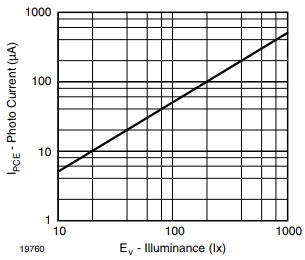
The range on this sensor is about 10 lux to 1000 lux which is very dim to about what an overcast day is. At almost dark light levels, the sensor can struggle between determining dark vs a little less dark.
The chart to the right is from the datasheet. It shows current flowing through the sensor relative to the illuminance (lux). With a little math, the sensor can be made into an inexpensive lux meter.
The program below simply reads the output of the sensor every second and prints the raw reading and volts to the Serial Monitor window. It also runs a calculation based on the datasheet graph that converts the reading into a lux value.
The sensor is connected to analog pin A0, but this can be changed to any convenient analog input. Also be sure to provide power and ground. We are using 5V in this example. If using 3.3V, be sure to change AREF to 3.3.
TEMT6000 Ambient Light Sensor Example Program
/*
   TEMT6000 Light Meter Program

  Simple program to read the analog output of the TEMT6000 and display
  the raw reading, voltage and the calculated Lux

  We are connecting sensor to analog input A0, but this can be any analog pin.
*/

int const TEMP6000_PIN = A0;
int const AREF = 5.0;       // set for 5.0 or 3.3 depending on voltage of uC
//===============================================================================
//  Initialization
//===============================================================================
void setup() {
  Serial.begin(9600);    // Initialize serial comm
}
//===============================================================================
//  Main
//===============================================================================
void loop() {

// The math is broken out into steps to make it easier to follow.
float sensor_value = analogRead(TEMP6000_PIN); // Get raw sensor reading
float volts = sensor_value * AREF / 1024.0;    // Convert reading to voltage
float amps = volts / 10000.0;             // Convert to amps across 10K resistor
float microamps = amps * 1000000.0;             // Convert amps to microamps
float lux = microamps * 2.0;                  // 2 microamps = 1 lux

// All the math above can also be replaced with the following formula
// assuming AREF is 5.0 volts.

    // float lux = sensor_value * 0.9765625;

Serial.print ("Raw ADC data: ");
Serial.print (sensor_value);
Serial.print ("  Volts: ");
Serial.print (volts);
Serial.print ("  Lux: ");
Serial.println (lux);

delay(1000);  // Take reading every second
}