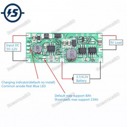
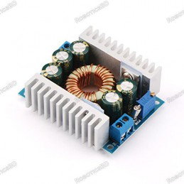
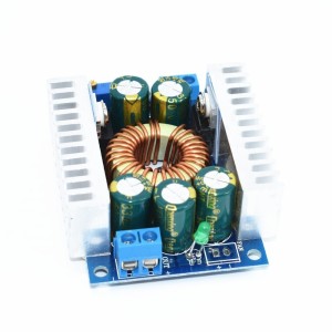
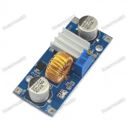
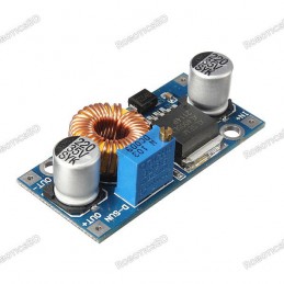
ZK-SJ4 is a DC adjustable constant voltage, constant current step down/up power supply module. Adjustable stable output voltage and current, set output current to meet the demand. It can be used as ordinary buck power supply module, charger and LED constant current driver. Support solar charging. Featured By RoboticsBD.
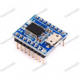
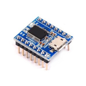
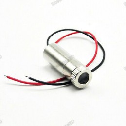
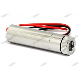
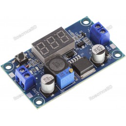
Product Images are shown for illustrative purposes only and may differ from the actual product.
RoboticsBD RoboticsBD RoboticsBD RoboticsBD RoboticsBD RoboticsBD RoboticsBD RoboticsBD RoboticsBD RoboticsBD
Applications:
- Ordinary power supply
- Battery charger
- LED drive power
- Instrument voltage display
- Test meter; 6>.Circuit test
- Power conversion. RoboticsBD
Features:
- High voltage resistant terminal.
- Support solar charging.
- Support under voltage protection.
- Support short circuit protection.
- Support automatic buck/boost voltage.
- Support solar charging.
- Support anti-backflow Protection
- Support charging function.
- Support working status indicator.
- High current, low heat.
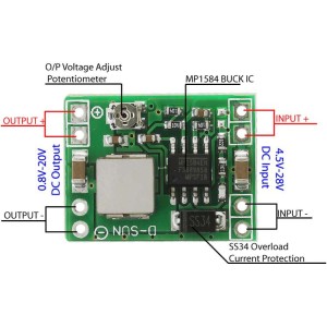
Potentiometer/LED introduction:
- CV Potentiometer:Adjust output voltage. Increase the output voltage when rotating clockwise.
- CC Potentiometer:Adjust output current. Increase the output current when rotating clockwise.
- CC LED:Red LED.Constant current output indicator. It enters the constant current state when the load current reaches the set current and CC constant current indicator turns ON. RoboticsBD
- FL LED:Green LED.Charged fully indicator.When battery is charged fully .It will turn ON. It will turn ON if output current is less than 0.2A when the Set Current is 2A(about 10%).
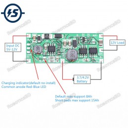
- CH LED: Blue LED.Charging indicator.It will turn ON when charging
RoboticsBD RoboticsBD RoboticsBD RoboticsBD RoboticsBD RoboticsBD RoboticsBD RoboticsBD RoboticsBD RoboticsBD
| General Specification |
| Product Name: | ZK-SJ4 4A Step Down/Up Power Supply Module |
| Product Number: | ZK-SJ4 |
| Working Voltage: | DC 4.8V-30V |
| Output Voltage: | DC 0.5V-30V |
| Output Current: | 4A (4A need heat sink; 3A is stable for long time) |
| Output Power: | 60W (60W need heat sink;35W is for 3A) |
| Conversion efficiency: | About 94% |
| Working current: | 30mA |
| Under voltage Protection: | Yes(Self-recovery) |
| Anti-backflow Protection: | Yes |
| Short Protection: | Yes |
| Work frequency: | 180KHz |
| Working Temperature range: | -20℃~85℃ |
| Working Humidity range: | 0%-95%RH |
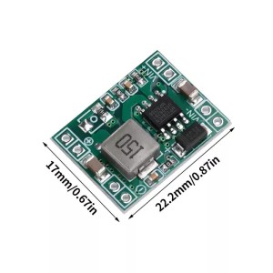
| Size: | 68*37*22mm |
| Heat sink size: | 48*16*10mm |
| Shipment Weight | 0.040 kg |
| Shipment Dimensions | 10 × 7 × 3 cm |
Please allow 5% measuring deviation due to manual measurement.
RoboticsBD RoboticsBD RoboticsBD RoboticsBD RoboticsBD RoboticsBD RoboticsBD RoboticsBD RoboticsBD RoboticsBD
Documentation (Using Steps):
1>.As a ordinary step down power module:
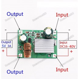
1.1>.Connect right input voltage at input terminal;
1.2>.Adjust CV constant voltage potentiometer to set output voltage according to require.
1.3>.Rotate CC potentiometer counterclockwise more than 10 turns at first.
1.4>.Test Output short circuit current by multimeter at 10A or 20A(Connect two Test Probes to output terminal on module)
1.5>.Rotate CC constant current potentiometer clockwise to set output current according to require overcurrent protection value.
1.6>.Test and using(E.g:Module’s maximum output current is 2A if display 2A on multimeter.Red LED indicator will turn on if output reach to 2A.Otherwise LED is OFF.)
1.7>.The output voltage will decrease due to the current sampling resistor at the output. The higher the current, the more the voltage is reduced.
2>.As a charger:
2.1>.Tops:Power module can not be used as charger module if it does not support constant current function.The voltage difference between the battery with insufficient voltage and the charger is very large.Causes excessive charging current even damage the battery.So it need keep charging in constant current mode to reaching a certain level.Then automatically switch back to constant voltage charging.
2.2>.Make sure floating charge voltage and charge current for battery.If the lithium battery’s parameter is 3.7V/2200mAh, then the float charge voltage is 4.2V, and the maximum charging current is 1C, which is 2200mA.
2.3>.Connect right input voltage at input terminal.(Note:Please don’t connect load during set parameter).
2.4>.Test output voltage by multimeter and adjust CC potentiometer to make sure output voltage reach to require floating charge voltage.(If charge a 3.7V lithium battery, adjust the output voltage to 4.2V)
2.5>.Rotate CC potentiometer counterclockwise more than 10 turns at first.
2.6>.Test Output short circuit current by multimeter at 10A or 20A(Connect two Test Probes to output terminal on module)
2.7>.Rotate CC constant current potentiometer clockwise to set output current according to require charge current value.
2.8>.Connect battery at output terminal and start to charging.
3>.As a high power LED constant current driver:
3.1>.Make sure LED working current and maximum working voltage.
3.2>.Connect right input voltage at input terminal.(Note:Please don’t connect load during set parameter).
3.3>.Test output voltage by multimeter at output terminal and adjust CV potentiometer to set output voltage to LED’s maximum working voltage.
3.4>.Rotate CC potentiometer counterclockwise more than 10 turns.
3.5>.Test Output short circuit current by multimeter at 10A or 20A(Connect two Test Probes to output terminal on module)
3.6>.Rotate CC constant current potentiometer clockwise to set output current according to require LED working current.
3.7>.Connect LED and test.
Notice:
- Input under voltage protection voltage is 4.2V. Module will self-recovery if input is more than 4.2V.
- Please rotate the CV potentiometer counterclockwise more than 20 turns if there is no output voltage.
- It is a DC power module, so it can not connect to AC power.
- Please connect input before connect battery when use as charge and make sure output voltage is higher than battery voltage.
- ’IN-’ and ‘OUT-’ can not be connect together, otherwise module can not support constant current output.
- Please make sure input power is greater than load power.
- Please step down output power if module is hot.
- Please read use manual and description before testing.
Package Includes:
1 x Solar Charger Controller Adjustable Step-Up / Down Automatic Power Module.
RoboticsBD RoboticsBD RoboticsBD RoboticsBD RoboticsBD RoboticsBD RoboticsBD RoboticsBD RoboticsBD RoboticsBD
RoboticsBD RoboticsBD RoboticsBD RoboticsBD RoboticsBD RoboticsBD RoboticsBD RoboticsBD RoboticsBD RoboticsBD