The LR7843 MOSFET Switch Control Module is a robust and efficient switching solution designed for controlling high-current loads in DIY electronics, robotics, and automation projects. Powered by the LR7843 N-channel logic-compatible MOSFET, it delivers ultra-low Rds(on) of just 3.3mΩ, allowing continuous load currents of up to 15A with minimal power loss and heat. Its built-in optoisolation ensures reliable operation and protection between control and load circuits, while compatibility with both 3.3V and 5V logic makes it easy to interface with popular microcontrollers such as Arduino, ESP32, STM32, and Raspberry Pi. Featuring compact design and convenient screw terminals, this module simplifies wiring and integration into your projects. Whether for motor control, LED driving, power distribution, or battery systems, this MOSFET module provides reliable, efficient, and safe switching performance. Featured By RoboticsBD.
Product Images are shown for illustrative purposes only and may differ from the actual product.
RoboticsBD RoboticsBD RoboticsBD RoboticsBD RoboticsBD RoboticsBD RoboticsBD RoboticsBD RoboticsBD RoboticsBD
Features:
High Current Handling – Supports up to 15A continuous load, ideal for demanding applications.
Ultra-Low Resistance – Only 3.3mΩ Rds(on), ensuring efficient performance with reduced heat.
Logic-Level Control – Works directly with 3.3V/5V microcontrollers without additional drivers.
Optoisolation Protection – Enhances circuit safety by isolating control signals from the power side.
Compact & Practical Design – Small PCB with screw terminals for easy integration and secure wiring.
Versatile Applications – Suitable for motor drivers, LED lighting systems, power management, and automation.
RoboticsBD RoboticsBD RoboticsBD RoboticsBD RoboticsBD RoboticsBD RoboticsBD RoboticsBD RoboticsBD RoboticsBD
Applications:
Motor speed and direction control in robotics and automation.
LED strips, lighting projects, and display systems requiring high-current switching.
Battery management systems and power distribution boards.
DIY electronics projects involving high-current switching with low-power control.
Automation systems requiring safe, opto-isolated switching modules.
RoboticsBD RoboticsBD RoboticsBD RoboticsBD RoboticsBD RoboticsBD RoboticsBD RoboticsBD RoboticsBD RoboticsBD
| General Specifications |
| MOSFET Model | LR7843 N-Channel Logic MOSFET |
| Control Voltage | 3.3V / 5V logic compatible |
| Continuous Current | Up to 15A |
| Rds(on) | 3.3mΩ (typical) |
| Isolation | Optoisolation between control and load |
| Input/Output Connections | Screw terminals |
| Suitable Controllers | Arduino, ESP32, STM32, Raspberry Pi |
| Module Type | Low-side switching |
| Shipment Weight | 0.0063 kg |
| Shipment Dimensions | 8 × 6 × 3 cm |
Please allow 5% measuring deviation due to manual measurement.
RoboticsBD RoboticsBD RoboticsBD RoboticsBD RoboticsBD RoboticsBD RoboticsBD RoboticsBD RoboticsBD RoboticsBD
Documentation:
Theory of Operation
The module includes a PC817 optoisolator which provides electrical isolation between the high powered MOSFET side and the logic signals used to control the module. If something goes wrong and you burn up the MOSFET, it should not damage the MCU being used to control it.
The MCU PWM input to the module drives the internal LED side of the optoisolator. This input includes a 1K ohm series current limiting resistor to keep the current through the LED at safe levels which allows the input to be driven by up to a 20V input or even higher if you are not using an MCU.
When the PWM input signal is low or disconnected, the internal LED in the optoisolator is off which in turn keeps the phototransistor output turned off. With the phototransistor off, the gate of the MOSFET is pulled to ground by a 4.7K resistor. This keeps the MOSFET turned off and the load is disconnected from ground and disbled.
A logic high on the PWM input turns on the internal optoisolator LED which turns on the phototransistor. This creates a voltage divider composed primarily of two 4.7K resistors. This biases the gate at 50% of the power supply voltage which turns on the MOSFET. If a 12V power supply is used, the gate will be at 6V.
Since the maximum gate voltage available to turn on the MOSFET is 50% of the power supply voltage, that limits the power supply to a minimum of about 6V. Power dissipation in the MOSFET will be higher with lower power supply voltages and a minimum power supply of 9V is recommended if trying to draw more than a few amps through the module.
When the MOSFET conducts, the load is connected to ground to complete the circuit and the load is powered up. This also provides a ground for the on-board LED which lights to indicate that the MOSFET is turned on. A 4.7K resistor limits current through the on-board LED to safe levels over the 6-36V operating range.

RoboticsBD RoboticsBD RoboticsBD RoboticsBD RoboticsBD RoboticsBD RoboticsBD RoboticsBD RoboticsBD RoboticsBD
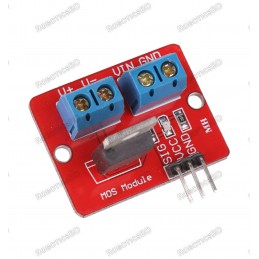
Module Connections
The module requires 3 connections. A logic signal to turn the MOSFET on/off; a DC power supply to power the device (load) being controlled and finally the load itself. Connectors are provided that can be soldered to be the board, but these connections can also be made by direct wiring if desired.
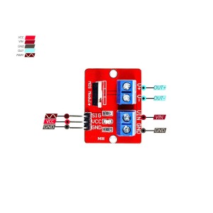
LR7843 MOSFET Control Module - Connections
Logic Signal Connections: The 2-pin connector on the right side is for making connections to the MCU. It has two holes on 4mm centers which support a 2 position screw terminal as well as two holes on 0.1″ centers that can alternatively support a standard male header which may be handy in a breadboard setup. The pins are labeled PWM for the signal and GND for the signal ground.
DC Load Power Supply: is connected to the 3-pin screw terminals marked + / LOAD / – on the back of the module. The positive lead of the power supply connects to + and the ground connection is hooked up to –. The module supports a load power supply of 6-28VDC
Load: The load which is being driven is connected to the screw terminals marked + and Load on the back of the module. The positive lead of the load connects to the + terminal and the negative lead of the load connects to the center load ground terminal.
The signal ground and the load ground connections are not connected together on the module due to the optoisolator being used to provide isolation between the MOSFET power circuit and the MCU.
1 x 2 Screw Terminal / Header (Logic Signal Input)
- PWM = Signal input (active HIGH).
- GND = Signal ground
1 x 3 Screw Terminal (Load Power Supply Connections)
- + = Connect to power supply (6-28V) being used to power the load
- – = Connect to power supply ground
1 x 3 Screw Terminal (Load Connections)
- + = Connect to positive lead of load (motor, LEDs, fan, etc)
- LOAD = Connect to negative lead of load
Physical Mounting: There are two 2mm diameter holes at the signal end of the board spaced 12mm apart if it is desired to physically mount it.

RoboticsBD RoboticsBD RoboticsBD RoboticsBD RoboticsBD RoboticsBD RoboticsBD RoboticsBD RoboticsBD RoboticsBD
OUR EVALUATION RESULTS:
These modules work well for basic ON/OFF operation such as for driving a solenoid or PWM control such as for dimming an array of LEDs and can handle a surprising amount of power given the small size. It is also possible to parallel these modules to further increase the power handling capability. Though the maximum current spec for the MOSFET is 161A, do not expect to run 161A through this small module as it will quickly overheat due to minimal heatsink capability of the small PCB.
One important point to take note of is that if an inductive load is being controlled, an external fly-back diode should be used to prevent possible damage when the load is switched off.
The chart below shows some example temperature measurements of the MOSFET with a load varying from 2.5A to 20A @ 12V. The logic drive signal varies from 100% duty cycle (always on) to 50% duty cycle or 25% duty cycle. The measurements are being taken with no airflow over the module and an ambient temperature of 22C. Since a 12V power supply is being used, the gate voltage is around 6V which gives pretty good performance.
In general, you should keep the MOSFET under about 100°C to keep it happy. For long-term use, 80°C or lower would be a better target.
| Load Amps | 12V Input @ 100% duty cycle | 12V Input @ 50% duty cycle | 12V Input @ 25% duty cycle |
| 5A | 34°C | 30°C | |
| 10A | 56°C | 39°C | 34°C |
| 15A | 97°C | 59°C | 40°C |
| 20A | | 88°C | 60°C
|
RoboticsBD RoboticsBD RoboticsBD RoboticsBD RoboticsBD RoboticsBD RoboticsBD RoboticsBD RoboticsBD RoboticsBD
TECHNICAL SPECIFICATIONS
| Maximum Ratings | | |
| VDS | Drain-Source Voltage | 30V max (28V recommended) |
| ID | Drain Current Max (Continuous) | 15A @ 12V |
| RDS(on) | Drain-Source On-Resistance | 3.3mΩ |
| Dimensions | (L x W x H) | 35 x 16 x 14mm (1.38 x 0.63 x 0.55″) |
| Country of Origin | | China |
| Datasheet | International Rectifier | IRLR7843 |
RoboticsBD RoboticsBD RoboticsBD RoboticsBD RoboticsBD RoboticsBD RoboticsBD RoboticsBD RoboticsBD RoboticsBD
Package Includes:
1 x LR7843 MOSFET Switch Control Module
RoboticsBD RoboticsBD RoboticsBD RoboticsBD RoboticsBD RoboticsBD RoboticsBD RoboticsBD RoboticsBD RoboticsBD
RoboticsBD RoboticsBD RoboticsBD RoboticsBD RoboticsBD RoboticsBD RoboticsBD RoboticsBD RoboticsBD RoboticsBD