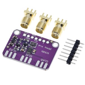
The 74HC4067 16-Channel Analog/Digital Multiplexer Module is a versatile and reliable solution for expanding the input/output capability of your microcontroller projects. With 16 bi-directional channels, it can be used as either a multiplexer or demultiplexer, handling both analog and digital signals such as sensors, switches, or serial data streams. Compatible with 3.3V and 5V logic, the module is controlled using four binary address pins (S0–S3) and one enable pin, allowing flexible signal routing. Featuring a low ON resistance of approximately 60–70Ω and up to 25mA per channel, this module is ideal for sequentially reading multiple inputs or managing signal distribution in robotics, automation, and electronic prototyping. Featured By RoboticsBD.
Product Images are shown for illustrative purposes only and may differ from the actual product.
RoboticsBD RoboticsBD RoboticsBD RoboticsBD RoboticsBD RoboticsBD RoboticsBD RoboticsBD RoboticsBD RoboticsBD
Features:
Provides 16 bi-directional channels for analog or digital signals.
Operates as a multiplexer or demultiplexer.
Compatible with both 3.3V and 5V logic systems.
Controlled by four binary address pins (S0–S3).
ON resistance of ~60–70Ω, supporting up to 25mA current.
Enable pin (active LOW) for easy control of channel activation.
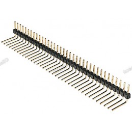
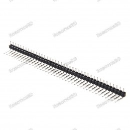
Compact design with male header pins included.
Expands MCU inputs/outputs for flexible project integration.
RoboticsBD RoboticsBD RoboticsBD RoboticsBD RoboticsBD RoboticsBD RoboticsBD RoboticsBD RoboticsBD RoboticsBD
Applications:
Expanding analog input channels for Arduino, ESP32, STM32, and other MCUs.
Reading multiple sensors, potentiometers, or switches sequentially.
Signal distribution and selection in robotics and automation.
Routing serial communications or digital signals.
Educational and prototyping projects requiring input/output expansion.
RoboticsBD RoboticsBD RoboticsBD RoboticsBD RoboticsBD RoboticsBD RoboticsBD RoboticsBD RoboticsBD RoboticsBD
| General Specifications |
| Product Type | Analog/Digital Multiplexer Module |
| IC Used | 74HC4067 |
| Channels | 16 bi-directional |
| Logic Compatibility | 3.3V / 5V |
| ON Resistance | ~60–70Ω (typical) |
| Max Current per Channel | 25mA |
| Control Pins | S0, S1, S2, S3 (address) + EN (enable) |
| Operating Voltage | 2V – 6V |
| Functionality | Multiplexer / Demultiplexer |
| Shipment Weight | 0.0033 kg |
| Shipment Dimensions | 4 × 2 × 2 cm |
Please allow 5% measuring deviation due to manual measurement.
RoboticsBD RoboticsBD RoboticsBD RoboticsBD RoboticsBD RoboticsBD RoboticsBD RoboticsBD RoboticsBD RoboticsBD
Documentation:
Module Connections
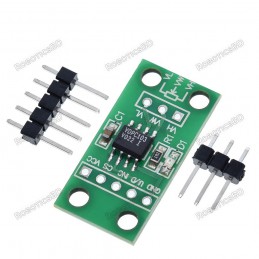
On the electronics module there are 2 rows of breakout points. These can be used to connect wires or header pins can be soldered in depending on the application.
1×8 Header
- SIG = Signal Input / Output. This will usually connect to an analog input or digital I/O on the microcontroller
- S3 = Binary Address Bit 3. The address bits (3…0) connect to 4 digital output pins on the microcontroller to select channel.
- S2 = Binary Address Bit 2
- S1 = Binary Address Bit 1
- S0 = Binary Address Bit 0
- EN = Enable. Internally pulled LOW to enable by default. Can be pulled HIGH to disable all channels.
- VCC = 2 to 6V. Usually connected to 5V or 3.3V to match the microcontroller power.
- GND = Ground, must be common with the microcontroller.
1×16 Header
- C15 = Channel 15
- C14 = Channel 14
- C1 = Channel 1
- C0 = Channel 0
RoboticsBD RoboticsBD RoboticsBD RoboticsBD RoboticsBD RoboticsBD RoboticsBD RoboticsBD RoboticsBD RoboticsBD
OUR EVALUATION RESULTS:
This is one of those devices that sounds complicated, but is actually easy to use. When using this device, it is perhaps easiest to think of it as a bank of 16 mechanical switches with one side of all the switches tied together with a built-in series resistor of 60-70 ohms that goes to a microcontroller analog or digital pin. The other side of the switches connect to analog or digital signals that you want to monitor or control. The main rule is that only one switch can be turned on at a time.
Since only one output can be active at a time these devices are generally most useful for sequentially reading multiple inputs rather than controlling outputs.
The board comes with male header pins. Whenever soldering header pins of this type, it is always recommended to insert the pins into a solderless breadboard while the module is being soldered to ensure the pins stay aligned with the breadboard spacing.
The example program below demonstrates some of its capability. It sets the device up on the A0 analog input pin and scans the 16 channels and prints out the analog value which will range from 0 to 1023. If the inputs are left floating, the readings will be random. If a pin is pulled low, it should read close to 0. If it is pulled to Vcc, it should read close to 1023.
RoboticsBD RoboticsBD RoboticsBD RoboticsBD RoboticsBD RoboticsBD RoboticsBD RoboticsBD RoboticsBD RoboticsBD
74HC4067 16-Channel Mux Program
/*  74HC4067 Analog / Digital Mux Example

   This is setup to read 1 of 16 analog inputs such as from analog sensors
   which is the most common use of this device.  The SIG pin can be connected to a
   digital pin if it is desired to work with digital data instead of analog.

   Accessing the device uses a table and small function to translate from channel 0-15 to the binary
   address to make life a little easier
*/
// Define pins used below
#define S0_PIN 4  // Use any 4 available digital pins for addressing the 74HC4067
#define S1_PIN 5
#define S2_PIN 6
#define S3_PIN 7
#define SIG_PIN A0  // Use any available analog pin.

// Table below is used to translate from 0-15 to binary address of device.
int channel_address_table[16][4] = {
  // s0, s1, s2, s3     channel
    {0,  0,  0,  0},    // 0
    {1,  0,  0,  0},    // 1
    {0,  1,  0,  0},    // 2
    {1,  1,  0,  0},    // 3
    {0,  0,  1,  0},    // 4
    {1,  0,  1,  0},    // 5
    {0,  1,  1,  0},    // 6
    {1,  1,  1,  0},    // 7
    {0,  0,  0,  1},    // 8
    {1,  0,  0,  1},    // 9
    {0,  1,  0,  1},    // 10
    {1,  1,  0,  1},    // 11
    {0,  0,  1,  1},    // 12
    {1,  0,  1,  1},    // 13
    {0,  1,  1,  1},    // 14
    {1,  1,  1,  1}     // 15
};
//===============================================================================
//  Initialization
//===============================================================================
void setup() {
  pinMode(S0_PIN, OUTPUT);  // Set addressing pins as outputs
  pinMode(S1_PIN, OUTPUT);
  pinMode(S2_PIN, OUTPUT);
  pinMode(S3_PIN, OUTPUT);

  Serial.begin(9600);          // Set Serial Monitor window comm speed
}
//===============================================================================
//  Main
//===============================================================================
void loop() {
  int mux_Value;
  // Step through each much channel and report what we are seeing
  for (int i=0; i<16; i++){
    Mux_Addr (i);
    delay(1000);  // Slow things down for readability and allow address to settle
    mux_Value = analogRead(SIG_PIN); // Read analog value from mux
    Serial.print("Ch");
    Serial.print(i);
    Serial.print(": ");
    Serial.println(mux_Value);
    //delay(1000);  // Delay 1 second to slow everything down for readability
  }
  Serial.println();
  delay(3000);  // Read the mux channels every 3 seconds
}

// Function to update the mux binary address bits given the channel number 0-15
void Mux_Addr (int ch_Addr)
{
    digitalWrite(S0_PIN, channel_address_table[ch_Addr][0]);
    digitalWrite(S1_PIN, channel_address_table[ch_Addr][1]);
    digitalWrite(S2_PIN, channel_address_table[ch_Addr][2]);
    digitalWrite(S3_PIN, channel_address_table[ch_Addr][3]);
RoboticsBD RoboticsBD RoboticsBD RoboticsBD RoboticsBD RoboticsBD RoboticsBD RoboticsBD RoboticsBD RoboticsBD
Package Includes:
1 x 74HC4067 16-Ch Analog / Digital Mux Module
RoboticsBD RoboticsBD RoboticsBD RoboticsBD RoboticsBD RoboticsBD RoboticsBD RoboticsBD RoboticsBD RoboticsBD
RoboticsBD RoboticsBD RoboticsBD RoboticsBD RoboticsBD RoboticsBD RoboticsBD RoboticsBD RoboticsBD RoboticsBD