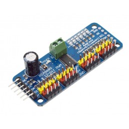
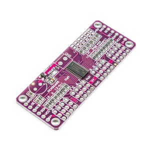
The 16-Channel PWM Servo Controller Shield is a powerful and convenient expansion for Arduino, designed to control multiple servos or PWM-driven devices using minimal I/O resources. Based on the PCA9685 PWM driver IC, it provides 16 independent 12-bit PWM outputs controllable via the I2C interface, freeing the microcontroller from continuous servo refresh operations. The board supports a PWM frequency range of 24Hz–1.5kHz, making it suitable for both LED dimming and servo motor control. It can operate with 3.3V or 5V logic levels, while servo power (V+) is supplied separately through the onboard terminal block (typically 5V). The shield features address selection jumpers (A0–A5), allowing multiple shields to stack for up to 62×16 channels. With a built-in prototype area, labeled pins, and compatibility with standard Arduino form factors, this shield is ideal for robotic arms, animatronics, lighting, and automation projects. Featured By RoboticsBD.
Product Images are shown for illustrative purposes only and may differ from the actual product.
This is the main power input when using with servos and is used to power the motors. This input has reverse polarity protection which may be a diode or a MOSFET transistor.
5V is typically applied to this connector. There is a red LED lit when power is applied to V+. There is a 2nd red LED lit when Vcc is applied to the module. You need both LEDs lit for the shield to operate.
Do not connect V+ to the Arduino 5V as the motors will create electrical noise that will cause issues for the Arduino. Also keep in mind the current draw of the servo motors that you select which can be quite high. Most Servos will draw at least 100mA or more each. If you are using this shield to drive LEDs, that can usually be done using the Arduino 5V as long as you stay within the current limits of the Arduino but larger arrays will require external power.
GND = Ground for motor power supply.
V+ = Voltage used to power Servo motors. 5V is typical and can be up to 6V
There is a spot to add a large electrolytic cap to V+ near the terminal block if additional filtering is needed.
Female Headers (Logic Connections)
The male/female stackable headers bring up all the I/O from an Arduino UNO, Leonardo or similar Arduino. The shield itself only uses the I2C data lines SDA and SCL but these lines are also available for other I2C devices.
SCL = I2C Clock. Connects to SCL pin on MCU
SDA = I2C Data. Connects to SDA pin on MCU
Note: For compatibility with older Arduinos that don’t have dedicated I2C lines, the SCL and SDA pins also connect to pins A4 and A5 which are used on the older boards for I2C. If you want to use A4 and A5 for other purposes with a newer R3 version Arduino, cut the traces to A4 and A5 on the back of the board to remove them from the I2C bus.
1×3 (x16) Male Headers (Servo Connections)
The output headers are numbered 0 thru 15 on the board. Each of these connections has the following pins.
PWM = Connects to the PWM pin on the servo motor. Servo wire color may be orange, yellow or white.
V+ = Connects to the power pin on the servo motor. Servo wire color is red
GND = Connects to the ground pin on servo motor. Servo wire color may be brown or black
Note: If using the module with LEDs:
LEDs connect between PWM and V+ with the cathode of the LED connecting to PWM. You can connect the LEDs the other way, but the PCA9685 is limited to 10mA source current in that configuration.
All PWM pins have a 220 ohm resistor in series which limit current to about 15mA depending on the LED. These will typically work fine as current limiting series resistors when driving standard low power indicator type LEDs and will keep the total power dissipation of the PCA9685 device within spec if all LEDs are driven full on.
These servo controllers work well for controlling multiple servos and makes connections much easier. Once a servo is set to a particular position with a simple I2C command, the controller takes care of the overhead required to keep the motor updated which frees up the microcontroller to do other stuff.
The header pins that insert into the MCU are the flat sided blade type, so some straightening of the pins is usually required to install the shield onto an MCU.
Servos expect to see a pulse about every 20mSec and the width of the pulse tells the servo where it should position its shaft. Most standard servos have a position range of approximately 0-180 degrees. They typically detect a pulse width of about 1mSec to be 0 degrees and a pulse width of 2mSec to be 180 degrees. Any pulse widths in-between these values can be used to set the servo to an arbitrary position. For instance, a pulse width of 1.5mSec will set the shaft to 90 degrees, 1.75mSec will be 135 degrees, etc.
The exact range of the servo can vary quite a bit between different types of servos. Instead of 0-180 degrees, some may only go 20-160 while others may go farther than 180. Interpretation of the pulse width such as 1.5mSec being 90 degrees can also vary quite a bit between servos. Some experimentation is generally needed to characterize the servos that you are using. In general, you don’t want the servos to be driven past a position that they can get to as that causes high stall currents and may damage the gears in the servo overtime. In the program below, there are two constants MIN_VALUE and MAX_VALUE that set the limits for the motor. These can be adjusted to suit the servos that you are working with.
To use this controller, you must initially set the PWM frequency which will remain constant. To generate a pulse every 20mSec as the servo expects requires a 50-60Hz PWM frequency to be set.
You then need to set the pulse width to move the servo to the position that you want it to be in. The PWM outputs are 12-bit which means their setting (pulse width) can range from 0-4096 which covers the range of 0 – 20mSec. If you have a 20mSec pulse width / 4096, the output has a resolution of about 4.88uSec, so if you want a 1.5mSec pulse width, that would be a setting of about 1.5mSec / .00488mSec = 307.
The program below uses the Adafruit_PWMServo library, so be sure to load it to use this program. It can be downloaded via the Arduino IDE.
The program simply exercises a single servo on channel 0 to verify the shield is basically working, but this can be changed to any channel by modifying this statement int servonum = 0;
Simply plug the shield into an Uno or compatible board and hook up 5V/Gnd to the screw terminal connections. Plug a servo into the channel 0 header. Ensure the PWM wire which is usually orange in color is plugged into the PWM pin. Both LEDs on the shield should be lit indicating both the board and servo have power. Once the program is downloaded, the servo should start cycling.
/* Exercise the PCA9685 Servo motor controller Rotates a single servo on channel 0 back and forth to test basic operation Uses Adafruit_PWMServoDriver.h library*/#include<Wire.h>#include<Adafruit_PWMServoDriver.h>Adafruit_PWMServoDriverpwm=Adafruit_PWMServoDriver(0x40);#defineSERVOMIN100// this is the 'minimum' pulse length count (out of 4096)#defineSERVOMAX440// this is the 'maximum' pulse length count (out of 4096)// Set for servo channel to testintservonum=0;//===============================================================================// Initialization//===============================================================================voidsetup(){Serial.begin(9600);Serial.println("Channel 0 Servo test");pwm.begin();pwm.setPWMFreq(60);delay(10);}//===============================================================================// Main//===============================================================================voidloop(){// Drive servo forward then back.for(intpulselen=SERVOMIN;pulselen<SERVOMAX;pulselen++){pwm.setPWM(servonum,0,pulselen);}delay(500);for(intpulselen=SERVOMAX;pulselen>SERVOMIN;pulselen--){pwm.setPWM(servonum,0,pulselen);}delay(1000);}
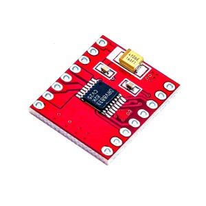
CW/CCW/short break/stop motor control modes Built-in thermal shutdown circuit and a low voltage detecting circuit Standby control to save power CW/CCW/short brake/stop motor control modes Operating Voltage(VDC): 15 Peak Current (A): 3.2 Continuous Current (A): 1.2 No. of Channels: 1
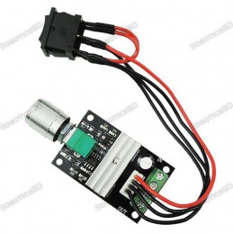
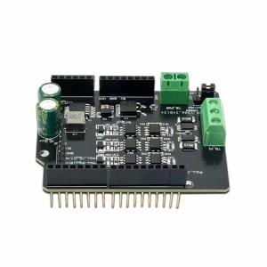
DC Motor Speed Controller PWM 12V Controls the speed of a DC motor using Pulse-Width-Modulation (PWM) Provides continuous current of 3A to the motor or DC load Includes a 3A fuse for protection Supports reverse connection of power supply
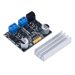
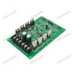
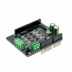
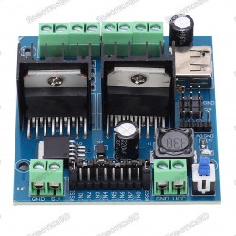
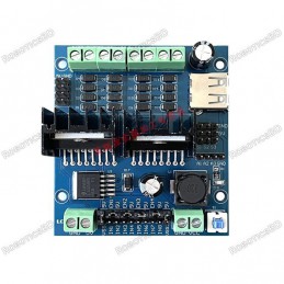
Dual-channel 10A DC motor driver module with independent control for each motor Supports PWM speed regulation and forward/reverse direction control Ideal for robotics, automatic curtains, and motion control systems Operates between 3V–18V DC, suitable for low-voltage, high-current motors MOS-based control circuit for efficient and stable performance with...
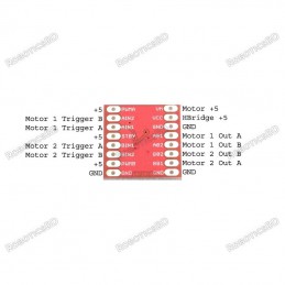
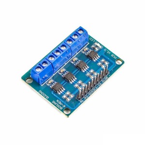
L9110S 4-Channel Motor Driver Board with four integrated H-Bridge chips Controls up to 4 DC motors or 2 stepper motors (4-wire, 2-phase) Wide operating voltage range: 2.5V to 12V DC Up to 0.8A current per channel 2.54mm pin spacing for easy microcontroller interfacing Ideal for robotics, smart cars, and automation projects
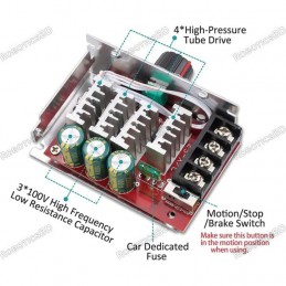
7-70V 30A PWM DC Motor Speed Controller Switch Wide voltage input range: 7-70V Maximum output current: 30A Speed control knob with switch function Adjustable potentiometer with flexible cable (15cm length) Includes a 30A fuse for motor interface protection Input power must be 1.5 times greater than the motor's rated power
We'll slide into your inbox when the product is back in stock.
You have successfully subscribed to this product
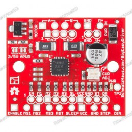
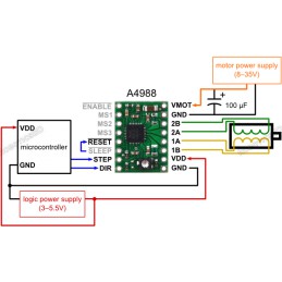
Bi-polar Microstepping Driver 2A/Phase Max 1.4-1.7A/Phase w/o Heatsink Max Motor Drive Voltage: 30V On-board 5V/3.3V Regulation Low RDS(ON) outputs Automatic current decay mode detection/selection Mixed and Slow current decay modes Synchronous rectification for low power dissipation Internal UVLO Crossover-current protection 3.3 and 5 V compatible logic...
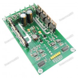
DC 3V-36V 15A Dual H-Bridge DC Motor Driver for high-current applications Can handle a maximum current of up to 30A for robust motor control Features PWM modulation with 0%-99% duty cycle for precise motor speed control Equipped with N-channel IRF3205 MOSFETs for enhanced performance and braking Ideal for driving high-current brushed DC motors in robotics...
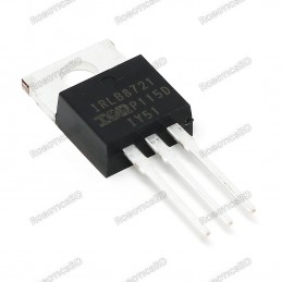
High-performance N-channel MOSFET with 30V / 60A switching capability Low 2.5V gate threshold voltage, perfect for direct logic-level control Standard TO-220 package fits breadboards and custom PCBs easily Compatible with 2.8V, 3.3V, and 5V microcontrollers (Arduino, ESP32, Raspberry Pi, etc.) Can handle up to 15A without heatsink (PWM use recommended)...
DRV8833 Dual DC Motor Driver Module with dual H-Bridge control Drives 2 DC motors or 1 stepper motor 1.5A continuous current per channel (4A peak) Wide operating voltage: 2.7V to 10.8V PWM control up to 100kHz for smooth speed regulation Ideal for robotics, smart cars, CNC, and battery-powered systems
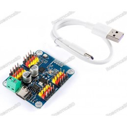
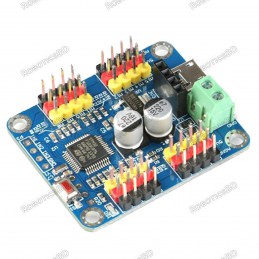
16 channels PWM servo motor driver controller board module Supports USB interface, TTL serial port, and Bluetooth communication Bluetooth communication can connect to Android phone or PC software Master chip STM32 series, frequency 48MHz Size 43.5x36mmx12mm, operating voltage 5V USB, TTL3.3V, servo motor supply 5-7.2V Channel 16, PWM accuracy 0.1ms
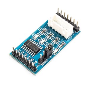
UL2003 4-Phase Stepper Motor Driver for precise unipolar motor control Built-in ULN2003A Darlington array for strong current driving capability Direct XH-5P socket support for 28BYJ-48 stepper motor 4-channel LED indicators for real-time signal monitoring Wide operating voltage range: DC 5V – 12V Ideal for robotics, CNC, automation, and embedded motion...
Arduino FOC Brushless Motor Driver Board optimized for precise BLDC control Designed for Field-Oriented Control (FOC) applications Dual INA240 high-precision current sensors for accurate feedback IR2104 gate drivers with adjustable voltage jumper Wide input voltage range 12V – 35V DC Compatible with Arduino UNO, MEGA, STM32 Nucleo & SimpleFOC Shield...
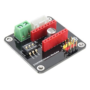
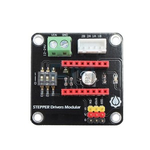
DRV8825 A4988 Stepper Motor Driver Expansion Board for easy stepper motor control Compatible with A4988 and DRV8825 driver modules Built-in DIP switch for quick microstepping configuration Supports 12V–30V input voltage for flexible power systems 5V logic interface for direct microcontroller connection Ideal for 3D printers, CNC machines, and robotics...
Dual Motor Control: Drive two DC motors or one stepper motor with precision. PWM Speed Regulation: Enables smooth and adjustable speed control. Wide Voltage Support: Operates on 5V to 46V power input. Built-In Indicators: Features current probes and direction indicators. Microcontroller Compatible: Works seamlessly with Arduino, Raspberry Pi, and more....
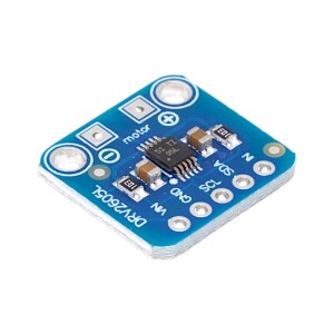
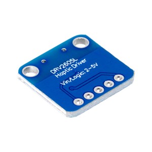
The DRV2605L Haptic Motor Controller Board is a compact and powerful solution for driving vibration motors with advanced haptic effects. Unlike simple on/off motor drivers, this controller features a built-in waveform library that enables rich vibration patterns such as clicks, pulses, ramps, and audio-synced effects.
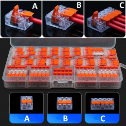
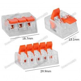
Wago Compatible 2 Port, 3 Port, 5 Port, 221 Splicing Connector, Lever-Nut Assortment Pocket Pack for All Wire 12-24 AWG You will get the 1 pcs of the model of your choice. A- 2 Port. B- 3 Port. C- 5 Port. Please Choose Size Below
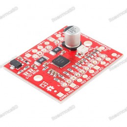
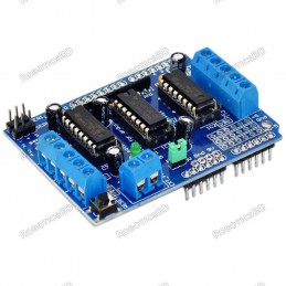
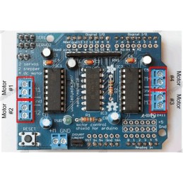
2 connections for 5V ‘hobby’ servos connected to the Arduino’s high-resolution dedicated timer 4 H-Bridges: L293D chipset provides 0.6A per bridge (1.2A peak) with thermal shutdown protection, internal kickback protection diodes. Can run motors on 4.5VDC to 25VDC. Up to 4 bi-directional DC motors with individual 8-bit speed selection (so, about 0.5%...
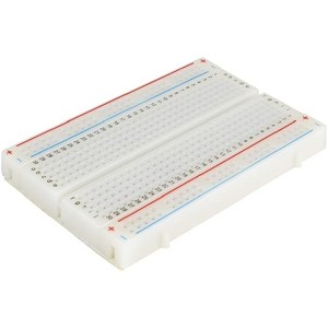
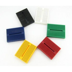
400 tie points 2 Power lanes, Total 100 tie points in power lanes 1 Double strip, Total 300 tie points Perfect for Arduino shield prototyping and testing Plastic housing, metal contact clips
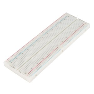
830 Solder-less Points Ideal for Experimenting With Circuit Design In Labs Compatible with resistance, diodes, transistors, LED’s, Capacitors and other types of electronic components Colored coordinates for easy components placement. Accept a variety of wire sizes 20-29 AWG
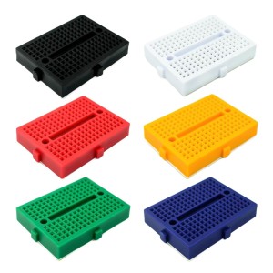
Tie-points: 170 (10×17) Size: 48 x 35 x 10 mm(LxWxH). Use: experimental, testing, robot Matching jumper, diameter 0.8mm Phosphor bronze nickel plated spring clips Accepts a variety of wire sizes (29-20 the AWG) **1 pcs Random Color
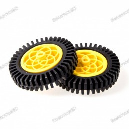
Tire with sponge liner for more strength With upgraded tire tread for greater friction New design wheel for better combination with the motor Diameter: 75 mm Width : 15 mm The material of Wheel: High-strength plastic The material of Tyre: Rubber Color: Yellow 1 pcs
Colour: Red, Green, Yellow, White, and Black, etc. Cable length: 40 cm. RoboticsBD Net weight: 50 gm. They are very useful for connecting components to wires. It is insulation covered clips connected to the wire from both ends. RoboticsBD *You will receive 1 pcs cable of random color.
Adjustable frequency PWM up to about 1.6 KHz 12-bit resolution for each output – for servos, that means about 4us resolution at a 60Hz update rate Configurable push-pull or an open-drain output The output enable pin to quickly disable all the outputs Terminal block for power input Reverse polarity protection on the terminal block input Green power-good LED
PCA9685 16-Channel PWM/Servo Driver with 12-bit resolution Controls up to 16 independent PWM outputs via I2C 4096-step precision for servo position or LED brightness PWM frequency adjustable from 24Hz to 1526Hz Supports up to 62 modules on one I2C bus Compatible with Arduino, ESP32, STM32, Raspberry Pi
16 channels PWM servo motor driver controller board module Supports USB interface, TTL serial port, and Bluetooth communication Bluetooth communication can connect to Android phone or PC software Master chip STM32 series, frequency 48MHz Size 43.5x36mmx12mm, operating voltage 5V USB, TTL3.3V, servo motor supply 5-7.2V Channel 16, PWM accuracy 0.1ms
BDT 2,490
BDT 2,490tax incl.
BDT 2,490tax excl.
BDT 2,490tax excl.
BDT 2,490tax incl.
BDT 2,490tax incl.
BDT 0Tax
BDT 2,490tax excl.
BDT 2,490tax excl.
BDT 0Tax
BDT 2,490tax incl.
Last items in stock
In stock:2
16-channel PWM servo controller shield powered by the PCA9685 chip for Arduino and compatible boards.
Provides 12-bit resolution PWM control with frequency range from 24Hz to 1.5kHz.
Drives up to 16 servos or LEDs using only two I2C pins (SDA/SCL).
Compatible with Arduino Uno, Mega, Leonardo, and similar boards.
Includes external power input, prototyping area, and address jumpers for multiple shield usage.