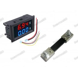
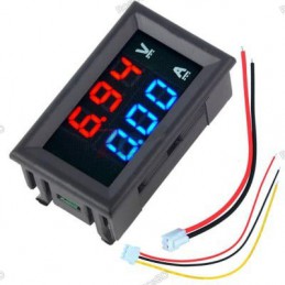
The Dual Display 0-100V / 0-10A Panel Meter is a compact and efficient digital measurement tool designed for real-time monitoring of both voltage and current in DC circuits. Featuring bright dual 0.28″ 7-segment LED displays in red and blue, it provides a clear and accurate reading with ±1 digit precision. The built-in current shunt supports low-side DC current measurement up to 10A, making it highly suitable for applications such as solar energy systems, DIY power supplies, battery monitoring, and other electronics projects. With an operating voltage range of 4.5V to 30V DC, this panel meter ensures flexibility and reliability in various setups. Featured By RoboticsBD.
Product Images are shown for illustrative purposes only and may differ from the actual product.
RoboticsBD RoboticsBD RoboticsBD RoboticsBD RoboticsBD RoboticsBD RoboticsBD RoboticsBD RoboticsBD RoboticsBD
Features:
Dual-function meter for simultaneous voltage (0-100V) and current (0-10A) monitoring.
Built-in low-side current shunt for simplified installation.
Clear dual LED display with separate colors for voltage and current.
Wide operating voltage range ensures compatibility with multiple DC systems.
Compact 0.28″ display for space-saving integration in panels.
High accuracy with ±1 digit error margin.
Durable and reliable design for continuous operation in hobby and professional use.
RoboticsBD RoboticsBD RoboticsBD RoboticsBD RoboticsBD RoboticsBD RoboticsBD RoboticsBD RoboticsBD RoboticsBD
Applications:
Monitoring solar cell voltage and current output.
Use in DIY or custom-built DC power supplies.
Battery charging and discharging monitoring.
Current draw analysis in robotics and embedded systems.
General-purpose voltage/current measurement for electronics projects.
| Voltage Measurement Range | 0 – 100V DC |
| Current Measurement Range | 0 – 10A DC (Low-side, with shunt) |
| Display Type | Dual 0.28″ 7-segment LED |
| Display Colors | Red (Voltage), Blue (Current) |
| Accuracy | ± 1 digit |
| Operating Voltage | 4.5V – 30V DC |
| Operating Mode | Self-contained panel meter |
| Recommended Use | Solar systems, battery monitoring, power supplies |
| Shipment Weight | 0.0303 kg |
| Shipment Dimensions | 6 × 5 × 3 cm |
RoboticsBD RoboticsBD RoboticsBD RoboticsBD RoboticsBD RoboticsBD RoboticsBD RoboticsBD RoboticsBD RoboticsBD
Please allow 5% measuring deviation due to manual measurement.
RoboticsBD RoboticsBD RoboticsBD RoboticsBD RoboticsBD RoboticsBD RoboticsBD RoboticsBD RoboticsBD RoboticsBD
Documentation:
Connections
The meter comes with two wiring harnesses that plug into connectors on the back of the module.
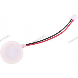
1×3 Wire Harness
The 3-wire small gauge harness is used to supply power to the module and to provide the voltage input for measurement.
Red Wire = Panel meter power. Connect to 4.5 to 30VDC
Black Wire = Panel meter ground
Yellow Wire = Connect to voltage to be monitored
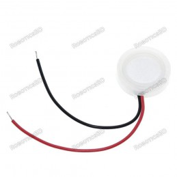
1×2 Wire Harness
The 2-wire large gauge harness is used for measuring current. The meter connects between the negative lead of the load and ground (low side of the load) for measuring current.
Red Wire = Connects to the negative lead of the load
Black Wire = Connects to ground
When wiring the module in, there are two basic connection schemes depending on if you want to power the meter from the same power source that you are monitoring or if you are using a separate power supply. Both are outlined below.
Using the same power supply
If the power supply being monitored is 30V or less, the meter can be powered off the supply that is being monitored. In this case, it is not necessary to connect the small black wire since the display ground is internally connected to the same point as the thick black wire.
Panel Meter Wiring Same Supply

Using a separate power supply
If monitoring a voltage that can go under 4.5V or over 30V, it is necessary to power the meter from a separate isolated power supply. In this case, the small black wire will need to connect to the ground of that separate power supply.

RoboticsBD RoboticsBD RoboticsBD RoboticsBD RoboticsBD RoboticsBD RoboticsBD RoboticsBD RoboticsBD RoboticsBD
Voltage Measurement
The yellow wire is the input for the voltage measurement.
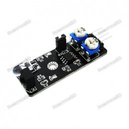
Accuracy of the voltage reading is ±1 digit. There is a trimmer pot on the back of the module labeled V or V_ADJ which can be used to calibrate the display against a reference meter if desired.
RoboticsBD RoboticsBD RoboticsBD RoboticsBD RoboticsBD RoboticsBD RoboticsBD RoboticsBD RoboticsBD RoboticsBD
Current Measurement
The large red and black wires pass the current through a built-in shunt in the module. The shunt may be a wire as shown in the pictures or a large 0.018 ohm SMD resistor. From the voltage drop across the shunt, the meter can calculate the current.
Accuracy of the current reading is ±1 digit. On some boards there is a trimmer pot on the back of the module labeled I_ADJ which can be used to calibrate the display against a reference meter if desired. Other boards do not have this adjustment.
The current can be measured in the positive direction only. If the display is not showing the current reading, ensure that the large black and red wires aren’t hooked up backwards.
Please Note: The meter is designed to connect to the low side of the load between the load and ground. It cannot be connected on the other side of the load between the positive voltage and the load or else the meter will be damaged.
RoboticsBD RoboticsBD RoboticsBD RoboticsBD RoboticsBD RoboticsBD RoboticsBD RoboticsBD RoboticsBD RoboticsBD
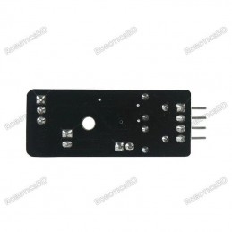
Resetting the Display
We have not seen this happen, but if the meter display gets hosed and the digits are indicating a completely incorrect value, it is possible to reset the meter on some versions of the meter.
To do this, locate the two holes in the corner of the board marked ‘TR’. With power off and no inputs on the voltage and current sense wires, short these two points on the board with something like tweezers and then apply power to the module using the small black and red wires. After a couple of seconds the display will reset and the short can be removed.
RoboticsBD RoboticsBD RoboticsBD RoboticsBD RoboticsBD RoboticsBD RoboticsBD RoboticsBD RoboticsBD RoboticsBD
OUR EVALUATION RESULTS:
There are a number of variations of this type of module in the market. The module we sell is the DSN-VC288 module, but there are still two flavors of circuit board. The pictures show both board versions.
We find these modules to be fairly accurate for the type of applications they are typically used in and they hold their accuracy over their measurement range well.
Because the meter current shunt is in series on the ground side of the load, under high current conditions the ground will raise slightly above 0V. This isn’t typically an issue, but something to keep in mind depending on your application.
RoboticsBD RoboticsBD RoboticsBD RoboticsBD RoboticsBD RoboticsBD RoboticsBD RoboticsBD RoboticsBD RoboticsBD
Package Includes:
1 x Dual Display 0-100V / 0-10A Panel Meter
RoboticsBD RoboticsBD RoboticsBD RoboticsBD RoboticsBD RoboticsBD RoboticsBD RoboticsBD RoboticsBD RoboticsBD
RoboticsBD Robotics