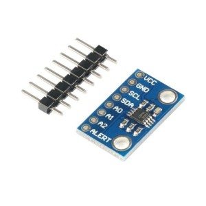
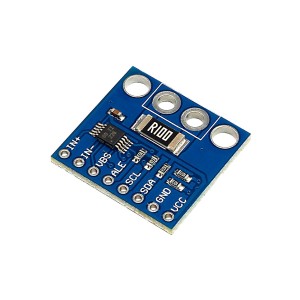
The INA219 DC Current Measurement Module provides a compact and accurate solution for monitoring current, voltage, and power in DC circuits. With its built-in 0.1Ω shunt resistor, it supports high-side current measurements up to 3.2A and load voltages up to 26VDC, making it ideal for robotics, battery monitoring, and motor control applications. Featuring a 12-bit ADC, the module delivers precise results with 0.8mA resolution over the I2C interface, while remaining compatible with both 3.3V and 5V logic microcontrollers. The I2C address can be configured for multiple modules in a single system, ensuring flexible integration. Compact and easy to use, the INA219 is a reliable choice for energy monitoring, protection systems, and embedded projects. Featured By RoboticsBD.
Product Images are shown for illustrative purposes only and may differ from the actual product.
The INA219 DC Current Measurement Module is inserted on the high side of the load, between the load and the load positive (+) power supply. This load power supply can range from 0V up to 26V.
The module itself is powered from 3-5V, so it is usually powered directly off the MCU.
The modules 3-5V logic supply should not be shared with motors running off the same voltage or else the device may reset due to electrical noise. If this happens, additional filter capacitance on the Vcc can be added near or on the module to try to minimize the problem.
Note that the INA219 module ground needs to be in common with the load ground or the voltage measurements will not be correct though the current measurement will be correct. If you don’t care about the voltage measurement, the grounds can be kept separate.
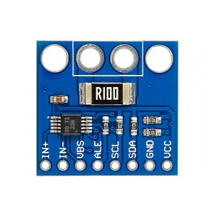
The module uses a 0.1 ohm 1% 2W current sense resistor which provides its 3.2A current handling capability. The low resistance keeps the voltage drop to a minimum. At the full rated current, the voltage drop across the current sense resistor would be 0.32V.
If you want to change the current measurement range, this resistor can be replaced with a resistor with a smaller or larger value. As an example a 0.01 ohm resistor will allow measurement of up to 32A with 8mA resolution. A 1 ohm resistor will lower the measurement range to 320mA with a 0.08mA resolution.
The module uses I2C for communications which makes hook-up to the MCU very easy.
The I2C default address is 0x40, but it can be changed to 0x41, 0x44 or 0x45 by bridging a couple of solder pads.
Changing the I2C address is generally not needed unless you are using more than one of these boards in a system or there is an address conflict with another I2C module. The address pins are labeled A0, A1 on the board.
Board 0: Address = 0x40. No jumpers needed. This is how module is shipped.
Board 1: Address = 0x41, Jumper A0 pads
Board 2: Address = 0x44, Jumper A1 pads
Board 3: Address = 0X45, Jumper both A0 & A1 pads
Note that these addresses are not sequential as you might expect, but these are the correct addresses.
The connections to the board can be made by soldering wires to the board, or the supplied headers and terminals can be solder on depending on the needs of the application. These can be soldered to either side of the board. For basic breadboard use, it generally works best to put the male header on the bottom of the board so that it can be inserted into the breadboard to hold it in place as shown in the pics.
There is a 6-pin header location on the assembly as well as a 2-pin screw terminal block for the main power connection.
1×6 Header
VCC = 3-5V power for the IN219 IC. Typically connects to 3.3 or 5V from the MCU.
GND = Ground connects to MCU and should also be in common with the ground for the load if voltage is being measured
SCL = Connects to SCL (I2C) on MCU
SDA = Connects to SDA (I2C) on MCU
VIN- = Alternate connection point for Vin- rather than using screw terminal
VIN+ = Alternate connection point for Vin+ rather than using screw terminal
1×2 Screw Terminal Block
VIN- = Connects to the positive terminal of the load.
VIN+ = Connects to the positive terminal of the power supply for the load
Note: If the current measurement is negative, these VIN connections have been reversed.
This block diagram shows the typical circuit connections.
These module work fairly well and can be used for applications such as monitoring the current and voltage to the motors of a robotic vehicle to keep an eye on the battery voltage and detect stall conditions.
The module current measurement has a theoretical 1.5% tolerance based on the max tolerance of the chip as well as the tolerance of the shunt resistor. In practice, expect up to about a 10% tolerance, so adequate for more coarse measurements such as detecting motor stall.
The example program below uses the Adafruit INA219 library which can be installed from the Library Manager of the IDE. The program below is based on their ‘getcurrent’ example program which is included with the library but with some modifications. When it is run, it outputs the following info.
Bus Voltage is the voltage going to the load before the shunt resistor.
Shunt Voltage is the voltage drop across the 0.1 ohm shunt resistor
Load Voltage is just the bus voltage minus the voltage dropped by the shunt, so it will be a little less than the Bus Voltage.
Current is the current as calculated by taking the Shunt Voltage and dividing it by the shunt resistance of 0.1ohm.
Power is the calculated power using the Load Voltage and Current.
Hookup is easy. Just connect the I2C SDA and SCL pins on the module to the same pins on the MCU. Also connect Vcc and ground pins to the MCU power and ground. Lastly connect that VIN- terminal to the positive terminal of the load and the VIN+ terminal to positive lead of the power source used to power the load. Ensure there is a common ground between the MCU and power source if you want to measure the voltage.
/** INA219 DC Current Sensor Module Test* Connect the SDA (I2C) of the MCU to the SDA pin on the module* Connect the SCL (I2C) of the MCU to the SCL pin on the module* Connect power (3.3 or 5V) of the MCU to the Vcc pin on the module* Connect ground of the MCU to the GND pin on the module.* Ensure the GND of the module is also connected to the ground of the load being measured*/#include<Wire.h>#include<Adafruit_INA219.h>Adafruit_INA219ina219;//===============================================================================// Initialization//===============================================================================voidsetup(void){Serial.begin(9600);while(!Serial){delay(1);// will pause Zero, Leonardo, etc until serial console opens}ina219.begin();// Initialize the INA219.}//===============================================================================// Main//===============================================================================voidloop(void){floatshuntvoltage=0;floatbusvoltage=0;floatcurrent_mA=0;floatloadvoltage=0;floatpower_W=0;shuntvoltage=ina219.getShuntVoltage_mV();// Read values from INA219busvoltage=ina219.getBusVoltage_V();current_mA=ina219.getCurrent_mA();loadvoltage=busvoltage-(shuntvoltage/1000);// Calculate voltage at loadpower_W=current_mA*loadvoltage/1000;// Calculate wattage of loadSerial.print("Bus Voltage: ");Serial.print(busvoltage);Serial.println(" V");Serial.print("Shunt Voltage: ");Serial.print(shuntvoltage);Serial.println(" mV");Serial.print("Load Voltage: ");Serial.print(loadvoltage);Serial.println(" V");Serial.print("Current: ");Serial.print(current_mA);Serial.println(" mA");Serial.print("Power: ");Serial.print(power_W);Serial.println(" W");Serial.println("");delay(2000);}
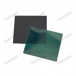
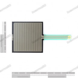
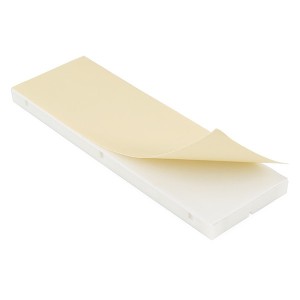
Visualize magnetic fields with ease using the field paper Large size of 100mm x 100mm for a clear and detailed view Micro-encapsulated film enables visualization of magnetic fields Suitable for use with any magnet Lightweight and compact for easy handling and storage
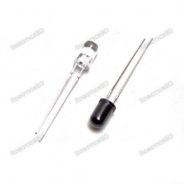
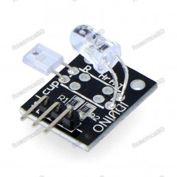
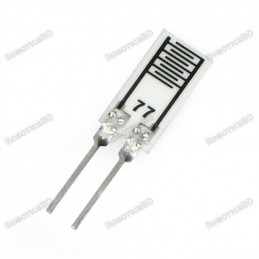
5mm Infrared Emitter and Detector pair for high-speed, high-sensitivity applications Infrared phototransistor with black epoxy for enhanced sensitivity Operating voltage: 2.3V, collector-emitter voltage: 2V Compact design ideal for obstacle detection and remote communication Sold as a pair: Blue/White LED as Emitter, Black LED as Detector
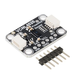
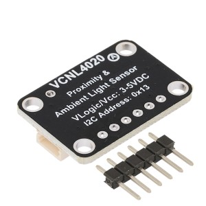
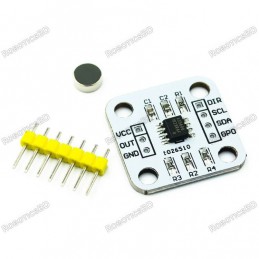
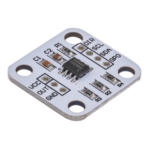
The VCNL4020 is a combined proximity and ambient light sensor module designed for short-range object detection and light level measurement. It integrates proximity sensing and illuminance detection in a single module with I2C communication, making it suitable for smart devices, automation systems, and embedded electronics projects.
MCP9808 High Accuracy I²C Digital Temperature Sensor with ±0.25°C precision. Wide temperature range: -40°C to +125°C with 0.0625°C resolution. I²C interface with adjustable addresses (up to 8 devices on one bus). Operates on 2.7V–5.5V, compatible with 3.3V and 5V logic systems. Ultra-low power consumption (200μA typical) ideal for battery-powered IoT....
LDR module 4 PIN Operating voltage 3.3V-5V Signal output indicator light. LDR module 4 PIN Able to detect ambient brightness and light intensity Adjustable sensitivity (via blue digital potentiometer adjustment)
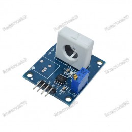
HW-671 WCS1800 Hall Current Sensor Module with over-current protection Current detection range: DC ±35A, AC 25A High-resolution current detection: 60mV/A Adjustable overcurrent threshold with a resolution of 1.5A Analog and TTL signal outputs for microcontroller integration Compact design with mounting holes for easy installation
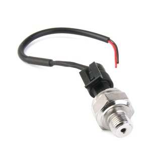
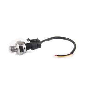
10MPa stainless steel pressure transducer with G1/4" threaded interface Designed for high-pressure monitoring applications High accuracy (±1.5%FS) with <2ms fast response Analog output: 0.5–4.5VDC @ 5V input for easy integration IP65-rated stainless steel housing ensures durability and stability Ideal for oil, gas, hydraulic, and industrial systems
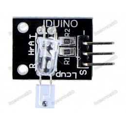
A sensor that allows you to measure your pulse with your finger using a phototransistor. The red LED lights up each time it detects a pulse. Powered by 5 V.
Programmable battery charger module for 6V–60V DC batteries up to 30A Compatible with lithium, lead-acid, and multi-cell battery packs (2S–14S) LCD display with real-time voltage, capacity, and status monitoring Built-in 30A relay for safe, automatic charge and discharge control Adjustable charging parameters with precise 0.1V accuracy Compact design with...
We'll slide into your inbox when the product is back in stock.
You have successfully subscribed to this product
The SHT41 is a high-accuracy digital temperature and humidity sensor module based on Sensirion’s fourth-generation SHT4x series. It provides precise environmental measurements over a wide operating range using a true I2C interface. This generic breakout is suitable for embedded systems, environmental monitoring, and precision measurement projects.
Easily customizable to a wide range of sizes Cost-effective Ultra-thin; 0.45 mm Robust; up to 10 million actuations Simple and easy to Integrate. RoboticsBD Force Sensitive Resistor Square High Quality
Analog air humidity sensor with resistance-based measurement Wide detection range: 10%–95% relative humidity (RH) High accuracy of ±3% RH at 25°C for reliable monitoring Compact size: only 10 × 5 × 0.65 mm (no case version) Operates across -20°C to +85°C for diverse environments Ideal for flexible integration into DIY and professional projects
We'll slide into your inbox when the product is back in stock.
You have successfully subscribed to this product
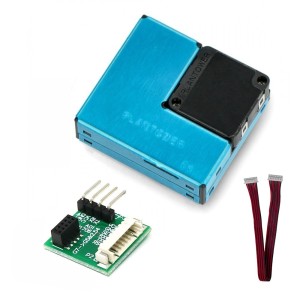
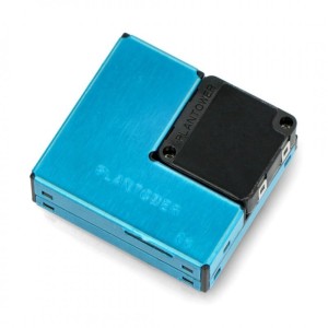
PlanTower PMSA003-C Laser Dust Sensor measures PM1.0, PM2.5, and PM10 concentrations for precise air quality monitoring. Utilizes laser light scattering technology to detect particles from 0.3 µm to 10 µm in size. Built-in low-noise fan ensures stable airflow and accurate measurements. UART communication interface for simple integration with...
The module can detect the surrounding environment of the humidity and temperature High reliability and excellent long-term stability The output from the digital output Humidity measuring range: 20%~90%RH(0~50 degree (temperature compensation). Temperature measuring range: 0~+50degree. Humidity measurement accuracy: ±5.0%RH. Temperature measurement...
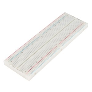
830 Solder-less Points Ideal for Experimenting With Circuit Design In Labs Compatible with resistance, diodes, transistors, LED’s, Capacitors and other types of electronic components Colored coordinates for easy components placement. Accept a variety of wire sizes 20-29 AWG
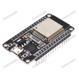
Built-in Flash: 32Mbit Power supply: 5V WiFi protocol: IEEE 802.11 b/g/n Peripheral interface: UART/GPIO/ADC/DAC/SDIO/PWM/I2C/I2S Logic level: 3.3V A high-quality USB cable is essential for this board to ensure sufficient current supply; otherwise, your board may not be recognized by the Windows Device Manager. Please avoid using mobile phone cables and...
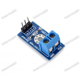
Voltage detection sensor module for measuring up to 25V DC using Arduino or microcontrollers Based on resistive voltage divider principle with secure screw terminal connections Expands Arduino’s 0–5V analog input range to 0–25V for accurate voltage monitoring High resolution of 0.00489V per step with 10-bit ADC support for precise readings Compatible with...
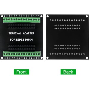
ESP32-S Screw Terminal Adapter for 38-pin ESP32-S development boards. Features screw terminals and female headers for secure, organized wiring. Provides direct access to all ESP32 I/O pins for easy prototyping and debugging. Ideal for IoT, automation, robotics, and educational projects. Clear pin labeling ensures quick and error-free connections. Compact...
High-precision voltage, current, and power monitoring module using INA226 sensor. 16-bit ADC resolution ensures accurate and stable real-time measurements. Supports I²C communication with Arduino, Raspberry Pi, ESP32, and STM32. Measures both high-side and low-side currents for flexible circuit integration. Wide input voltage range up to 36V with...
Designed to extract, amplify, and filter small biopotential signals. Leads-Off Detection. Shutdown Pin. LED Indicator. Analog Output. 3.5 mm Jack for Biomedical Pad Connection. RoboticsBD
High hardness, Corrosion protection. Waterproofness and High precision. The mode of its output signal:0-5V(Voltage signal). supply voltage: DC 12-24V. Power consumption:Voltage MAX≤0.3W. Start wind speed:0.4-0.8m/s.
Onboard STM8S103 high-performance microprocessor With digital tube display Valid Measurement Distance: 3-400cm Display Unit: cm Maximum Input Voltage: 5VDC 2.54mm White Socket: 5V power interface.
BDT 450
BDT 450tax incl.
BDT 450tax excl.
BDT 450tax excl.
BDT 450tax incl.
BDT 450tax incl.
BDT 0Tax
BDT 450tax excl.
BDT 450tax excl.
BDT 0Tax
BDT 450tax incl.
In-Stock
In stock:45
INA219 DC current and voltage measurement module with I2C interface
Measures high-side current up to 3.2A with 0.8mA resolution
Supports load voltages from 0–26VDC
Powered by 3–5V, compatible with both 3.3V and 5V logic MCUs
Integrated 0.1Ω shunt resistor ensures accurate measurements
Adjustable I2C address for multiple modules on the same bus