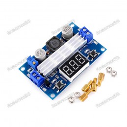
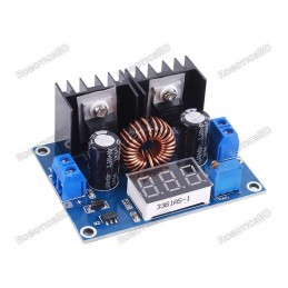
The 5A Adjustable Step Down CC / CV Module is a versatile and compact DC-DC buck converter designed with the XL4015 IC, providing both constant voltage (CV) and constant current (CC) control. Equipped with a convenient built-in display, it allows users to monitor real-time output voltage and current easily. With an input range of 5V – 30V and an adjustable output range of 0.8V – 29V, this module is perfect for applications such as battery charging, constant current LED driving, or serving as a small adjustable lab power supply. It delivers up to 5A with proper cooling, or 3A in natural convection, making it an efficient and flexible solution for hobbyists, makers, and engineers who need precision control in compact projects. Featured By RoboticsBD.
Product Images are shown for illustrative purposes only and may differ from the actual product.
RoboticsBD RoboticsBD RoboticsBD RoboticsBD RoboticsBD RoboticsBD RoboticsBD RoboticsBD RoboticsBD RoboticsBD
Features:
Adjustable Output Voltage & Current – Provides fine-tuned control over both voltage (0.8V–29V) and current (up to 5A).
Built-in Display – Integrated screen shows real-time output voltage and current for quick monitoring.
High Current Capability – Supports up to 5A with adequate cooling, or 3A without additional cooling.
XL4015 Step-Down Converter – Efficient buck converter design for reliable DC power regulation.
Versatile Input Range – Accepts 5V to 30V input, suitable for various power sources.
Compact & Durable – Small form factor makes it easy to integrate into projects.
RoboticsBD RoboticsBD RoboticsBD RoboticsBD RoboticsBD RoboticsBD RoboticsBD RoboticsBD RoboticsBD RoboticsBD
Applications:
Battery Charging – Ideal for charging Li-ion, Li-Po, or lead-acid batteries with adjustable current limiting.
LED Driver – Works as a constant current LED driver for high-power LED projects.
DIY Power Supply – Can be used as a bench power supply for hobby electronics.
Embedded Projects – Powers microcontrollers, modules, and sensors with stable voltage.
Prototyping & Testing – Great tool for engineers and makers testing circuits requiring current limiting.
RoboticsBD RoboticsBD RoboticsBD RoboticsBD RoboticsBD RoboticsBD RoboticsBD RoboticsBD RoboticsBD RoboticsBD
| Module Type | DC-DC Step-Down (Buck) Converter |
| IC Chip | XL4015 |
| Input Voltage Range | 5V – 30V |
| Output Voltage Range | 0.8V – 29V |
| Output Current | Up to 5A (with cooling), 3A (without cooling) |
| Display | Built-in voltage and current LED display |
| Mode | Constant Voltage (CV) / Constant Current (CC) |
| Recommended Current | 1.5A – 3A for stable operation |
| Dimensions | 6 × 3 × 3 cm |
| Shipment Weight | 0.0507 kg |
| Shipment Dimensions | 6 × 3 × 3 cm |
Please allow 5% measuring deviation due to manual measurement.
RoboticsBD RoboticsBD RoboticsBD RoboticsBD RoboticsBD RoboticsBD RoboticsBD RoboticsBD RoboticsBD RoboticsBD
Documentation:
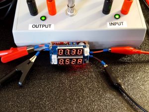
Output Display
The display shows the output voltage on the top display in the format XX.XU. The right most digit displays a ‘U’ to represent Voltage.
The bottom display shows the output current in the format X.XXA. The rightmost digit is an ‘A’ to represent Amps.
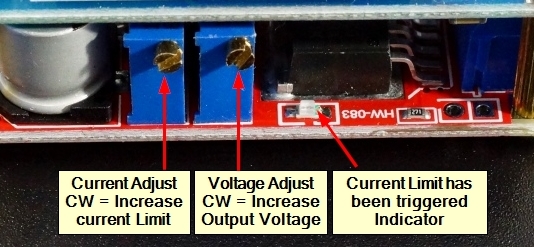
There are two on-board multi-turn pots for adjusting output voltage and setting current limiting.
RoboticsBD RoboticsBD RoboticsBD RoboticsBD RoboticsBD RoboticsBD RoboticsBD RoboticsBD RoboticsBD RoboticsBD
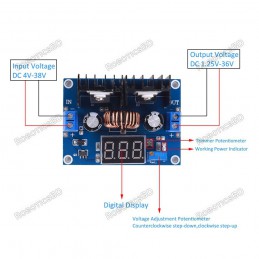
Output Voltage Adjustment
The potentiometer towards the middle of the module is used for adjusting the output voltage which is shown on the top LED display.
Turning the pot CW increases the the output voltage, turning it CCW decreases the output voltage. The maximum output voltage will be about 1V less than the input voltage. The minimum output voltage will be about 0.8V.
The output voltage can be set before a load is connected.
RoboticsBD RoboticsBD RoboticsBD RoboticsBD RoboticsBD RoboticsBD RoboticsBD RoboticsBD RoboticsBD RoboticsBD
Current Limit Adjustment
The other pot is for adjusting the current limit set-point. The current being drawn is shown on the bottom LED display.
Turning the pot CW increases the current limit (amount of current the module will supply) while turning it CCW decreases the current limit.
If current is being limited by the module, the red LED on the side of the module with the adjustment pots comes on.
Note: If the module is in current limit mode, the output voltage will decrease, and the display numbers will start to jump around. This is normal because when in current limit mode, the module outputs a varying waveform.
To preadjust the current limit before hooking it up to a load, it is recommended to short the output terminals of the module with a DVM set for its 10A DC Current mode. This will safely draw the maximum amount of current the module will allow based on its current setting and show the amount of current being drawn. You can then use the current limit adjustment pot to set the current limit to whatever value you need.
RoboticsBD RoboticsBD RoboticsBD RoboticsBD RoboticsBD RoboticsBD RoboticsBD RoboticsBD RoboticsBD RoboticsBD
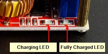
Status LEDs
There are 2 additional LED status indicators on the side opposite the adjustment pots.DC-DC Step Down CC & CV Module - Indicator LEDs
The LED on the left comes on to indicate that charging is occurring if the module is being used to charge a battery.
The LED on the right comes on to indicate that charging is complete as the current being drawn from the module is reduced toward zero. It switches the LEDs between the two states when the current reaches approximately 10% of the current limit setting.
RoboticsBD RoboticsBD RoboticsBD RoboticsBD RoboticsBD RoboticsBD RoboticsBD RoboticsBD RoboticsBD RoboticsBD
Input Power
Input power is applied to the left end of the bottom board which is the end with the 3-pin white connector. Connections are made using a 2-pos screw terminal. Access to the screws is through holes in the top board using a small screwdriver.
1×2 Terminal Block (Input Power)
IN+ = Input power 5 – 30VDC
IN- = Ground for input power
Note: The module does not have a reverse polarity protection diode, so ensure that the power is connected with the proper polarity or damage will result.
RoboticsBD RoboticsBD RoboticsBD RoboticsBD RoboticsBD RoboticsBD RoboticsBD RoboticsBD RoboticsBD RoboticsBD
Output Power
Output power available on the opposite (right) end of the module. It also uses screw terminal type connections to allow easy connection of wires for hookup.
1×2 Terminal Block (Output Power)
OUT+ = Output power 0.8 – 29VDC
OUT- = Ground for output load. The input and output grounds must be kept separate.
RoboticsBD RoboticsBD RoboticsBD RoboticsBD RoboticsBD RoboticsBD RoboticsBD RoboticsBD RoboticsBD RoboticsBD
TTL Interface Connector
The 3-pin white JST style connector brings out the TTL serial interface from the STM8S003F3 micro that is used on the display board. In theory, it is possible to retrieve the voltage and current readings from the device through this interface though it appears to be pretty clunky. For more info on this, check out this article
Note: The 2-pin connector is not used.
RoboticsBD RoboticsBD RoboticsBD RoboticsBD RoboticsBD RoboticsBD RoboticsBD RoboticsBD RoboticsBD RoboticsBD
OUR EVALUATION RESULTS:
These are useful modules that work fairly well with a few caveats as noted below.DC-DC Step Down CC & CV Module - Operation
The rated measurement accuracy of the displayed output is 0.1%. Since it uses a 10-bit DAC for measurements along with other component tolerances, it cannot achieve that stated accuracy in practice. If you are doing something that requires precision adjustment of the voltage or current, you might want to double-check the measurements with a meter.
The white connectors can be in the way if you are trying to mount the module into an opening. If you are not using the serial interface, these connectors can be removed by desoldering or simply cutting them off.
The module senses current using a large 0.05 ohm resistor on the bottom of the board. The resistor connects between the ‘-‘ terminals of the input and output connectors to sense current. This means that the input and output cannot share a common ground or else the current sensing will not work.
Use care not to short the output if the voltage is set to its minimum setting of about 0.8V using the adjustment pot. If that happens, the output current will rail to 5A no matter what the current limit is set to and the module will start to heat up pretty quickly. If this happens, just increase the voltage setting a bit using the pot and it will correct itself.
The module inconveniently has no mounting holes. Since the standoffs are used for making electrical circuit connections between the two modules, do not be tempted to use those screws for mounting unless it is to a non-conductive surface.
RoboticsBD RoboticsBD RoboticsBD RoboticsBD RoboticsBD RoboticsBD RoboticsBD RoboticsBD RoboticsBD RoboticsBD
Package Includes:
1 x 5A Adjustable Step Down CC / CV Module
RoboticsBD RoboticsBD RoboticsBD RoboticsBD RoboticsBD RoboticsBD RoboticsBD RoboticsBD RoboticsBD RoboticsBD
RoboticsBD RoboticsBD RoboticsBD RoboticsBD RoboticsBD RoboticsBD RoboticsBD RoboticsBD RoboticsBD RoboticsBD