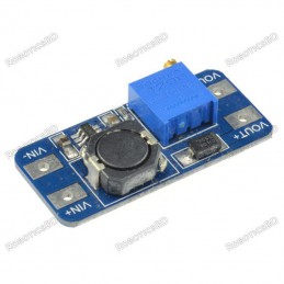
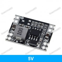
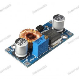
The MP2315 Mini Adjustable DC-DC Step-Down Module is a high-efficiency buck converter designed to step down voltages from 4.5V to 24V into a precise output of 0.8V to 22V. With a compact design and robust MP2315 IC, it delivers a continuous 1.5A output current and supports short bursts up to 2A, making it ideal for compact electronics, embedded systems, and portable devices. The module ensures excellent load and voltage regulation, protecting sensitive circuits from fluctuations. Additionally, it features an output enable pin compatible with both 3.3V and 5V logic, built-in over-current and thermal shutdown protection, and the option to configure fixed voltage outputs by simple solder pad adjustments. Using low ESR ceramic capacitors, it ensures durability without electrolytic capacitor aging, making it a reliable choice for long-term use. Featured By RoboticsBD.
Product Images are shown for illustrative purposes only and may differ from the actual product.
RoboticsBD RoboticsBD RoboticsBD RoboticsBD RoboticsBD RoboticsBD RoboticsBD RoboticsBD RoboticsBD RoboticsBD
Features:
Ultra-miniature design for space-saving integration into compact projects.
Adjustable output voltage (0.8–22V) suitable for multiple applications.
Stable performance with excellent load and voltage regulation.
High current capability with 1.5A continuous and 2A peak output.
Flexible logic compatibility with output enable pin supporting 3.3V & 5V systems.
Built-in safety features including over-current and thermal shutdown protection.
Optional fixed output mode via simple solder pad reconfiguration.
Low ESR ceramic capacitors for improved stability and long service life.
RoboticsBD RoboticsBD RoboticsBD RoboticsBD RoboticsBD RoboticsBD RoboticsBD RoboticsBD RoboticsBD RoboticsBD
Applications:
Power supply for Arduino, ESP32, Raspberry Pi, and other microcontrollers.
Ideal for robotics, IoT, and embedded system projects.
Battery-powered devices requiring efficient voltage regulation.
Prototyping circuits that demand precise adjustable voltage.
Replacing bulky linear regulators in low-voltage applications.
DIY electronics and portable device power solutions.
RoboticsBD RoboticsBD RoboticsBD RoboticsBD RoboticsBD RoboticsBD RoboticsBD RoboticsBD RoboticsBD RoboticsBD
| Input Voltage Range | 4.5V – 24V |
| Output Voltage Range | 0.8V – 22V (Adjustable) |
| Continuous Output Current | 1.5A |
| Peak Output Current | 2A |
| Regulation | Excellent load and voltage regulation |
| Logic Compatibility | Output enable pin (3.3V / 5V logic) |
| Protection Features | Over-current & thermal shutdown |
| Capacitors Used | Low ESR ceramic capacitors |
| Fixed Voltage Option | Yes (via solder pad modification) |
| Module Type | Buck (Step-Down) Converter |
| Shipment Weight | 0.0019 kg |
| Shipment Dimensions | 3 × 3 × 3 cm |
Please allow 5% measuring deviation due to manual measurement.
RoboticsBD RoboticsBD RoboticsBD RoboticsBD RoboticsBD RoboticsBD RoboticsBD RoboticsBD RoboticsBD RoboticsBD
Documentation:
RoboticsBD RoboticsBD RoboticsBD RoboticsBD RoboticsBD RoboticsBD RoboticsBD RoboticsBD RoboticsBD RoboticsBD
Voltage Adjustment
Using Adjustable Output
As-shipped, the module has a single-turn potentiometer for adjustment of the output voltage.
Turning the pot CW increases the output voltage while turning it CCW decreases the output voltage. Because the pot is single-turn, setting an exact voltage is typically not possible, but the setting can easily be set to within a couple percent of the target value which is fine for most applications. For example when targeting 5V, expect to hit 4.95 – 5.05V.
The lowest output voltage is approximately 0.8V. The upper limit of the adjustment range will depend on the input voltage and is typically about 0.6V less than the input voltage. With a 12V input for instance, the upper output limit will be approximately 11.4V.
Using Fixed Output
Optionally, a trace on the back of the module can be cut and one of several solder pads can be bridged to have the converter output a fixed voltage of 1.8V, 2.5V, 3.3V, 5V, 9V or 12V.MP2315 Mini Adjustable DC-DC Step-Down Module - Jumpers
Cutting the small trace requires a sharp Exacto knife or razor blade and either good eye-sight or a magnifier of some kind. Solder bridging the pads will require a soldering iron with a fairly small tip.
If it is desired to return to the adjustable output, the ADJ pads can be shorted.
In our testing, the accuracy of the fixed output voltages was within 5% on all settings and was very close on the 3.3 and 5V settings as shown in the table below.

| Voltage Setting | Measured Output |
| 1.8V | 1.71V |
| 2.5V | 2.39V |
| 3.3V | 3.29V |
| 5V | 4.97V |
| 9V | 8.77V |
| 12V | 11.65V |
RoboticsBD RoboticsBD RoboticsBD Rob
RoboticsBD RoboticsBD RoboticsBD RoboticsBD RoboticsBD RoboticsBD
Module Connections
These are very compact boards with 4 solder connections on standard 0.1″ centers. A male header strip is provided which can be soldered to the board for making connections.
1 x 4 Header
EN = Enable. Active HIGH and pulled HIGH on the module. Pull LOW to disable the module output.
IN+ = Input voltage
GND = Ground
VO+ = Output voltage
Keep in mind when using these modules on a solderless breadboard that with higher currents the voltage drop through standard breadboard jumpers can become significant. Ensure you use larger gauge wire, keep the wires short and/or double up on the wires to minimize any voltage drop.
RoboticsBD RoboticsBD RoboticsBD RoboticsBD RoboticsBD RoboticsBD RoboticsBD RoboticsBD RoboticsBD RoboticsBD
OUR EVALUATION RESULTS:
These are actually pretty impressive little modules for their size and have excellent voltage and load regulation with a very low ripple voltage.
Ripple voltage was measured @ 30mV with an increase up to 50mV with no load on the module.
Voltage regulation is spec’d at ±0.5%. With the output adjusted to 5V, varying the input voltage over the range of 6 – 24V resulted in a 0.04V change in the output.
Load regulation is spec’d at ±1%. With input of 12V and output adjusted to 5V, varying the load over the range of 0.0A to 2.0A resulted in a 0.1V change in the output
The table below gives some thermal results with an ambient temp of approx 25°C and the module operating at different input and output voltages and current loads of 1A, 1.5A and 2A.
In general at 1A, the module is very comfortably limping along. At 1.5A is it starting to get pretty warm but is still in a comfortable range. At 2A it is starting to get pretty toasty and in some cases too warm as indicated in red.
While this measurement is being taken on the converter IC, the inductor thermals are tracking similarly. For long-term reliable use, I would not recommend running more than about 1.5A on this module. For short-term use like for breadboarding, you can pull 2A without any problems.
RoboticsBD RoboticsBD RoboticsBD RoboticsBD RoboticsBD RoboticsBD RoboticsBD RoboticsBD RoboticsBD RoboticsBD
Package Includes:
1 x MP2315 Mini Adjustable DC-DC Step-Down Module
RoboticsBD RoboticsBD RoboticsBD RoboticsBD RoboticsBD RoboticsBD RoboticsBD RoboticsBD RoboticsBD RoboticsBD
RoboticsBD RoboticsBD RoboticsBD RoboticsBD RoboticsBD RoboticsBD RoboticsBD RoboticsBD RoboticsBD RoboticsBD