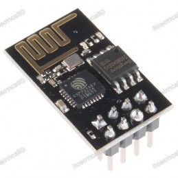
The ESP8266 Witty Cloud ESP-12F WiFi Module is a compact and versatile WiFi-enabled development board designed for IoT, automation, and sensor-based applications. Powered by the ESP8266 32-bit Tensilica processor running up to 160MHz, it offers 4MB flash memory, 11 digital I/O pins, and integrated WiFi 802.11 b/g/n connectivity. The board features a built-in RGB LED, LDR light sensor, and pushbutton, allowing easy testing and standalone functionality without extra components. Equipped with a CH340 USB-to-serial converter, it supports seamless programming through the Arduino IDE or NodeMCU firmware. Its modular dual-board structure enables users to detach the USB interface for embedded applications. Ideal for smart home, wireless data logging, or educational IoT development, the ESP8266 Witty Cloud ESP-12F combines flexibility, power, and ease of use in a single compact module. Featured By RoboticsBD.
Product Images are shown for illustrative purposes only and may differ from the actual product.
All of the Digital I/O support PWM and interrupts except pin 16 which does not support interrupts. In addition they can be configured to have pull-up or pull-down resistors. Though there are 11 digital I/O pins, 2 are typically reserved for use as the TX/RX lines if serial communications are used which leaves 9 digital I/O for other uses. Some of these 9 pins are connected to the on-board LEDs, but can also be used for other purposes if needed.
PWM range by default is 0-1023 rather than the typical 0-255 found on Arduino. The range can be modified using the command analogWriteRange (255) which sets the range between 0-255.
The PWM frequency is 1kHz by default. Similarly it can be modified using the analogWriteFreq(500) to set the frequency to 500 Hz as one example.
The pins are labeled GPIOx. When using with Arduino IDE, the digital pin number is the samethe pin number, so GPIO2 is referenced as just ‘2’.
The small blue on-board LED is connected to pin 2 (GPIO2).
The on-board general purpose pushbutton on the top board is connected to pin 4 (GPIO4).
The RGB LED is common cathode and so lights when driven HIGH. It is connected to the following pins:
Pin 15 (GPIO15) = RGB Red LED
Pin 12 (GPIO12) = RGB Green LED
Pin13 (GPIO13) = RGB Blue LED
Per spec, the digital I/O is limited to 3.3V, but the mfr has made statements that the digital pins are in fact 5V tolerant and there are many installations using the module directly connected to the logic lines of 5V MCUs, so use your own judgment.
The analog input A0 (ADC) is a single 10-bit ADC input which is connected to the LDR (Light Dependent Resistor).
The LDR has a dark resistance of about 2.5K and is in series with a 470 ohm resistor to form a voltage divider that feeds the ADC input. The LDR is connected to the Vcc side of the voltage divider and the 470 ohm resistor connects to ground. As the light intensity increases, the LDR resistance decreases and therefore the voltage on the ADC input increases.
By measuring the voltage, the relative brightness of the light falling on the sensor can be determined.
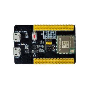
The board uses the CH340 chip on the bottom board for USB communications, so the bottom USB must be used for programming or communicating with the module.
If you have any issues with connecting to the board, you may need to download a driver for the CH340. Just search for Arduino CH340 driver and you will find a number of sources for drivers depending on what Windows or Mac operating system you are using.
The module comes preloaded with the NodeMCU software that accepts the standard AT command set.
It also can be programmed in C using the Arduino IDE and is how the modules are most often used. An example program is shown down below. If a program is download via the IDE, it will overwrite the NodeMCU software or whatever else was loaded before. If that is a problem for what you want to do, the NodeMCU software can always be reloaded.
There are many instructions for installing and using ESP8266 based boards with the Arduino IDE, but here is a short-hand version. Note that once the ESP8266 board type is added to the IDE, there will be many more items added to the Tools drop down menu.
Open Preferences window and enter the following into the ‘Additional Board Manager URLs’ field: “http://arduino.esp8266.com/stable/package_esp8266com_index.json“.
Under Boards Manager, install ESP8266 by ESP8266 Community.
Under Tools/Boards select “Adafruit Feather HUZZAH ESP8266“.
Set Upload Speed to “115200“.
Select the port that the board is attached to. In my case it happened to be COM3
In the Serial Monitor window, set comm rate to 115200 and line ending to Both NL & CR
Here is what it looks like on my setup.
To test whether the board is basically working and you can communicate with it using the preloaded NodeMCU software, you can open a Serial Monitor Window and simply enter ‘AT‘ into the serial monitor top window and hit ENTER. The board should return with ‘OK‘. That indicates the board is alive and the setup is working.
If you don’t get the OK:
Ensure that you have the USB cable plugged into the bottom USB connector, not the top.
Make sure that you have the correct Comm Port selected.
Verify the serial monitor window is set to a baud rate of 115200 and the line ending is set to Both NL & CR.
The micro USB connector has a very small footprint and solder pads which makes it popular for small MCUs where space is limited. As with any MCU that uses the micro USB connector, some care should be taken not to put excessive strain on the USB cable or it is possible for the connector to be dislodged from the board.
The Witty Cloud (and ESP8266 processors in general ) have a couple of software quirks to be aware of compared to working with a standard Arduino.
First is that the compile and download time when using the IDE tends to be longer than for typical Arduino boards. This is especially true the first time a program is compiled or if the build options are changed which require a complete recompile. Subsequent compiles do run faster.
The second thing is that the module does not like long delays in code and it may cause the module to do a watchdog software reset. This is because the module has a network stack to handle the WiFi and that needs to be serviced regularly by the processor. An example of what not to do would be using something like a tight DO/WHILE loop waiting for a button to be pressed.
For instance in the example program down below, if you were to check the button using code like this which blocks the program until the button is pushed, you will run into this problem as it does not allow any free time for the processor to go off and reset the watchdog timer on occasion, so it thinks it has locked up and resets itself.
Do {
btn_Status =digitalRead (BUTTON_PIN)
} while (btn_Status==HIGH)
If the module keeps resetting every couple of seconds, look for this blocking type of issue in your code. This can be resolved by inserting the yield() function into the loop as that function lets the processor go off and take care of other business before returning to the loop.
Using the delay() function does not create the same blocking issue because the delay() function internally calls the yield() function every so often.
The program below is based on one of the sample programs ‘WiFiScan’ that is available once the ESP8266 boards are loaded into the IDE. It sends the list of networks found to the Serial Monitor window.
The version here uses the built-in pushbutton to initiate the scan for any available WiFi networks and turns on the on-board LED while a scan is in process. It also monitors the light level on the LDR and adjusts the brightness of the RGB green LED based on the amount of light that the LDR sensor is detecting. If you put your finger on the LDR, the RGB LED should go out.
The only connection that needs to be made is the USB cable to the USB connector on the bottom board. Ensure HUZZAH ESP8266 is selected as the board type in the IDE and the correct COM port is selected. Once the program is downloaded, open the Serial Monitor window and ensure that the baud rate is set to 115200. Once you press the pushbutton on the edge of the top board, a scan of the available WiFi networks will be displayed.
ESP8266 Witty Cloud ESP-12F WiFI Module Example Program
/* This sketch demonstrates how to scan for available WiFi networks.
A button input is used to initiate the scan and the on-board LED
is lit to indicate when a scan is in process
On each loop, also check the analog input connected to the LDR and adjust
the brightness of the RGB Green LED to match the measured brightness.*/#include"ESP8266WiFi.h"constintBUTTON_PIN=4;// Define pin the button is connected toconstintON_BOARD_LED=2;// Define pin the on-board LED is connected toconstintRGB_G_PIN=12;// RGB Green LEDconstintLDR_PIN=A0;// Define the analog pin the LDR is connected to//===============================================================================// Initialization//===============================================================================voidsetup(){pinMode(ON_BOARD_LED,OUTPUT);// Initialize the LED_BUILTIN pin as an outputpinMode(BUTTON_PIN,INPUT_PULLUP);// Initialize button pin with built-in pullup.digitalWrite(ON_BOARD_LED,HIGH);// Ensure LED is offSerial.begin(115200);// Set comm rate to 115200// Set WiFi to station mode and disconnect from an AP if it was previously connectedWiFi.mode(WIFI_STA);WiFi.disconnect();delay(100);Serial.println("Setup done");}//===============================================================================// Main//===============================================================================voidloop(){intbtn_Status=HIGH;intlightIntensity;lightIntensity=analogRead(LDR_PIN);// Read the light intensityanalogWrite(RGB_G_PIN,map(lightIntensity, 40,1023,0, 1023));btn_Status=digitalRead(BUTTON_PIN);// Check status of buttonif(btn_Status==LOW){// Button pushed, so do somethingSerial.print("Light Intensity Reading: ");Serial.println(lightIntensity);Serial.println("scan start");digitalWrite(ON_BOARD_LED,LOW);// Turn LED ON// WiFi.scanNetworks will return the number of networks foundintn=WiFi.scanNetworks();Serial.println("scan done");if(n==0)Serial.println("no networks found");else{Serial.print(n);Serial.println(" networks found");for(inti=0;i<n;++i){// Print SSID and RSSI for each network foundSerial.print(i+1);Serial.print(": ");Serial.print(WiFi.SSID(i));Serial.print(" (");Serial.print(WiFi.RSSI(i));Serial.print(")");Serial.println((WiFi.encryptionType(i)==ENC_TYPE_NONE)?" : Unsecure":" : Encrypted");delay(10);}}Serial.println("");digitalWrite(ON_BOARD_LED,HIGH);// Turn LED Off}}
Quad-band 850/900/1800/1900MHz Inner MT3337 GPS receiver, -165dBm precision, control on a same serial port. Earphone/ microphone outputs on a card or external 32-ohm speaker + supports voice calls with an electret microphone. Sending and receiving SMS.
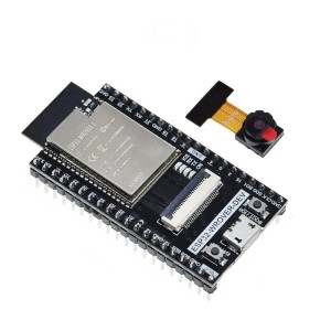
ESP32-S3-EYE AI Development Board with camera and LCD Dual-core ESP32-S3 with 8MB Flash + 8MB PSRAM Built-in 2MP camera for image recognition 1.3-inch LCD for real-time display output Integrated microphone for voice processing Supports ESP-WHO AI framework and Wi-Fi image streaming
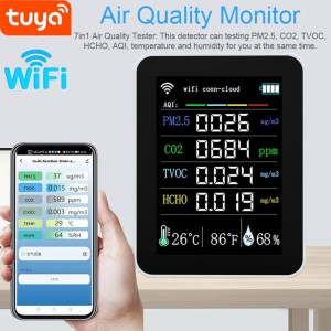
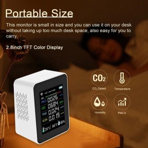
Simultaneous monitoring of PM2.5, CO2, TVOC, HCHO, AQI, temperature, and humidity. 2.8-inch TFT color display for clear detection data. Connects to Tuya App for real-time monitoring and historical data analysis. Portable size for easy desk placement and portability. Equipped with high-precision VOC sensors and low power consumption. PM2.5 Sensor: This...
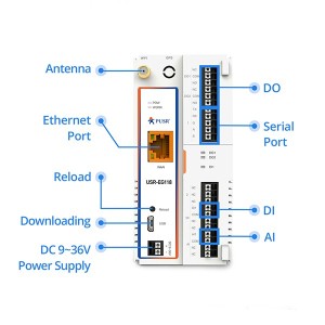
Arduino PLC IoT Gateway USR-EG118 powered by ESP32-WROVER-E dual-core 240MHz MCU Supports RS485/RS232, Ethernet, Wi-Fi & BLE 4.2 for full industrial connectivity 4MB PSRAM + Up to 8MB SPI Flash for stable IoT data processing Compatible with Arduino IDE & ESP-IDF for fast and flexible development Multiple network modes (AP, STA, AP+LAN, AP+WAN) for...
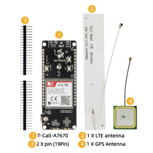
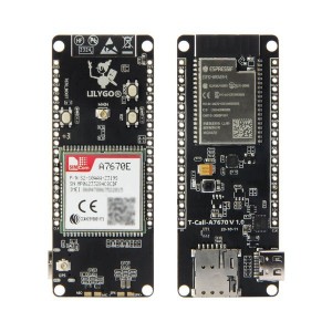
ESP32-WROVER-E based development board with integrated A7670E LTE/GSM module Supports 4G and 2G cellular connectivity for global IoT applications Includes Wi-Fi 802.11 b/g/n and Bluetooth 4.2 (BLE + BR/EDR) connectivity Equipped with 4MB Flash and 8MB PSRAM for complex applications Provides multiple interfaces: I2C, SPI, UART, SDIO, I2S, CAN Ideal for...
We'll slide into your inbox when the product is back in stock.
You have successfully subscribed to this product
Simultaneous monitoring of PM2.5, CO2, TVOC, HCHO, AQI, temperature, and humidity. 2.8-inch TFT color display for clear detection data. Connects to Tuya App for real-time monitoring and historical data analysis. Portable size for easy desk placement and portability. Equipped with high-precision VOC sensors and low power consumption. PM2.5 Sensor: This...
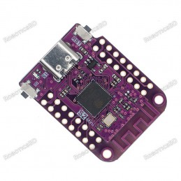
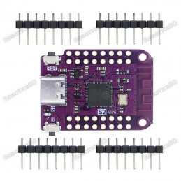
ESP32-S2 based WIFI development board Features S2FN4R2 WIFI IC Equipped with 4MB FLASH and 2MB PSRAM Type-C USB connectivity 27 digital input/output pins with support for interrupt/pwm/I2C/single wire ADC, DAC, I2C, SPI, UART, USB OTG
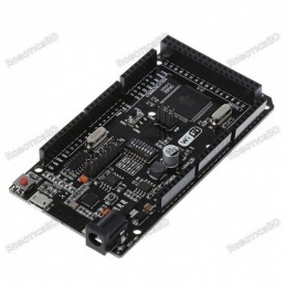
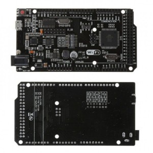
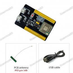
Arduino compatibility Full integration USB-TTL converter 32 Mb flash memory Dual microcontrollersA high-quality USB cable is essential for this board to ensure sufficient current supply; otherwise, your board may not be recognized by the Windows Device Manager. Please avoid using mobile phone cables and instead use the recommended cable available here:...
802.11 b/g/n Standards Wi-Fi Direct (P2P), soft-AP 1MB Flash Memory Integrated low power 32-bit CPU could be used as an application processor A-MPDU & A-MSDU aggregation & 0.4ms guard interval Wake up and transmit packets in < 2ms Standby power consumption of < 1.0mW (DTIM3) RoboticsBD
This ESP32-WROVER-DEV development board is a powerful Wi-Fi and Bluetooth enabled controller designed for camera-based and IoT applications. It is built around a dual-core ESP32 SoC running up to 240 MHz, delivering strong processing performance for image capture, wireless transmission, and real-time control.
The Thermal-90 ESP32-S3 IR Imaging Camera Module is a wide-angle wireless thermal camera designed using the ESP32-S3-WROOM-1 processor and an 80×62 hybrid IR sensor. It captures thermal radiation and generates real-time surface temperature images, ideal for scenarios requiring broader coverage.SKU:30139Part No.:Thermal-90 Camera ESP32 ModuleBrand:Waveshare
Test and development board for E83-2G4M03S Bluetooth Mesh module Pre-soldered with E83-2G4M03S for immediate use All IO ports accessible for easy integration and testing Built-in CH340X USB-to-serial chip for direct communication Stable performance, reliable operation, and developer-friendly design Compact design with lightweight build for lab and field...
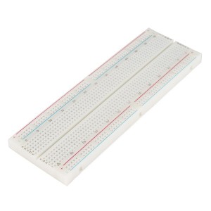
830 Solder-less Points Ideal for Experimenting With Circuit Design In Labs Compatible with resistance, diodes, transistors, LED’s, Capacitors and other types of electronic components Colored coordinates for easy components placement. Accept a variety of wire sizes 20-29 AWG
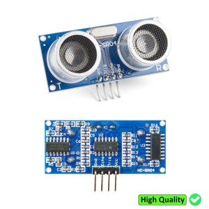
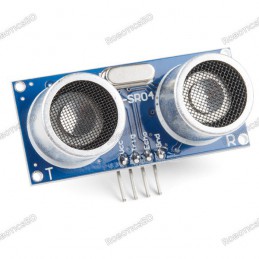
This is the HC-SR04 ultrasonic distance sensor. This economical sensor provides 2cm to 400cm of non-contact measurement functionality with a ranging accuracy that can reach up to 3mm. Each HC-SR04 module includes an ultrasonic transmitter, a receiver and a control circuit. There are only four pins that you need to worry about on the HC-SR04: VCC (Power),...
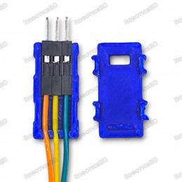
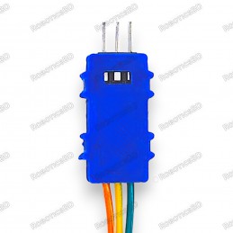
Tidy up your workspace and organize your jumper wires with this handy 3D printed housing for Dupont connectors. Securely holds up to 3 jumper wires (3-pin) for easy access and strain relief. No soldering required - simply snap the connector housings into place. Compatible with Arduino, Raspberry Pi, sensors, LED strips, and various DIY electronics projects.
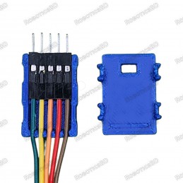
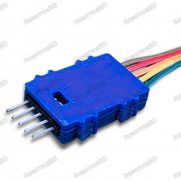
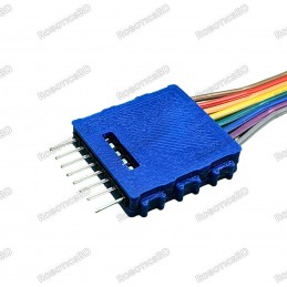
Tidy up your workspace and organize your jumper wires with this handy 3D printed housing for Dupont connectors. Securely holds up to 5 jumper wires (5-pin) for easy access and strain relief. No soldering required - simply snap the connector housings into place. Compatible with Arduino, Raspberry Pi, sensors, LED strips, and various DIY electronics projects.
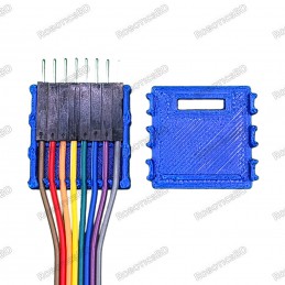
Tidy up your workspace and organize your jumper wires with this handy 3D printed housing for Dupont connectors. Securely holds up to 8 jumper wires (8-pin) for easy access and strain relief. No soldering required - simply snap the connector housings into place. Compatible with Arduino, Raspberry Pi, sensors, LED strips, and various DIY electronics projects.
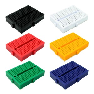
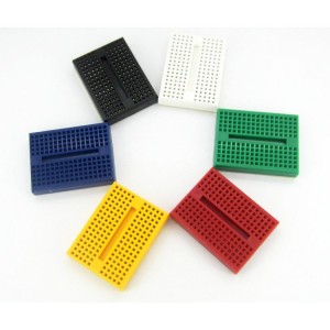
Tie-points: 170 (10×17) Size: 48 x 35 x 10 mm(LxWxH). Use: experimental, testing, robot Matching jumper, diameter 0.8mm Phosphor bronze nickel plated spring clips Accepts a variety of wire sizes (29-20 the AWG) **1 pcs Random Color
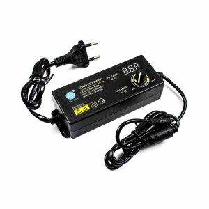
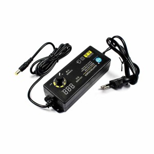
Adjustable voltage power supply from 3V to 12V DC, supporting up to 5A output current. Built-in LED display for real-time voltage monitoring and precise adjustment. High-efficiency 60W switching power supply ensures stable and reliable performance. Includes overload, short-circuit, and over-voltage protection for safety. Suitable for DC motors, LEDs,...
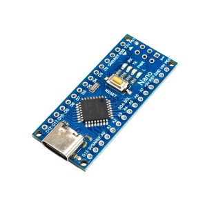
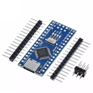
Arduino Nano-compatible development board powered by ATmega328P microcontroller. Features a modern USB Type-C connector for power and programming. Equipped with CH340G USB-to-serial chip for stable communication. Compact, breadboard-friendly design for easy prototyping. Fully compatible with Arduino IDE and existing Nano libraries. Ideal for IoT,...
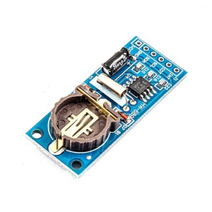
Low-power PCF8563 Real-Time Clock (RTC) and calendar module for accurate timekeeping. Communicates via I2C interface, compatible with Arduino, Raspberry Pi, ESP32, STM32, and more. Features alarm, timer, and programmable clock output functions. Built-in oscillator capacitor for stable performance without extra components. Ultra-low power consumption of...
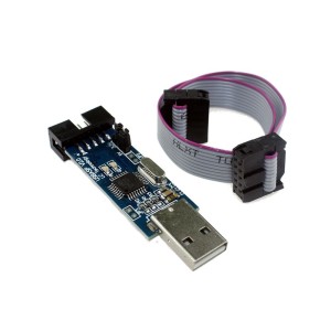
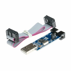
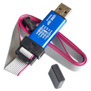
Compatible with ATMEL AVR Processors: Supports ATMega, Tiny, Classic, CAN, and PWM series chips. Bootloader Recovery: Easily restore Arduino bootloaders. In-Circuit Programming: USB ASP programmer designed for seamless ATMEL AVR microcontroller programming. Firmware-Only USB Driver: No additional USB controllers required. Compact and Reliable: Built with...
Compatible with ATMEL AVR Processors: Supports ATMega, Tiny, Classic, CAN, and PWM series chips.Bootloader Recovery: Easily restore Arduino bootloaders.In-Circuit Programming: USB ASP programmer designed for seamless ATMEL AVR microcontroller programming.Firmware-Only USB Driver: No additional USB controllers required.Compact and Reliable: Built with...